Method for combining concrete base of offshore supporting structure and steel pipe pile

A supporting structure and concrete technology, which is applied in foundation structure engineering, sheet pile walls, buildings, etc., can solve the problems of increased wave force, long time, and difficult construction of the supporting structure, and achieve the effect of firm combination and prevention of water pollution

Inactive Publication Date: 2016-10-26
EPS ENG
View PDF6 Cites 0 Cited by
  • Summary
  • Abstract
  • Description
  • Claims
  • Application Information

AI Technical Summary

Problems solved by technology

The support structure of offshore wind power generation is different from the support structure of onshore wind power generation. Because it is set at sea, it is greatly affected by external forces generated by waves, tides, and wind. The force increases, whereby there is a problem of reducing the stability of the supporting structure
[0010] In addition, the prior art, that is, Korean Patent Laid-Open No. 10-2013-0047950 (2013.05.09.) is a method for setting up a support structure of an offshore wind turbine, which is characterized in that it includes the following steps: the step of fixing the lower support structure. The lower supporting structure composed of a plurality of hollow lower supporting parts is fixed on the seabed; the connecting step of the intermediate supporting structure is to connect the hollow guiding parts of the intermediate supporting structure composed of a plurality of hollow guiding parts with each of the hollow lower parts respectively. The support member is inserted and aligned to connect the lower support structure and the intermediate support structure; and the upper support structure setting step is to mount the equipment for power generation on the lower part of the upper upper support structure and the upper part of the intermediate support structure The connection also includes a plurality of steel pipe piles. When performing the insertion and alignment connection between the lower support structure and the intermediate support structure, the gap between the two structures is completed through cement grout pouring, and the lower support structure penetrates The hollow part of each of the hollow lower support members is inserted into the seabed, whereby the lower support structure is fixed on the seabed, and piling work is performed to connect the lower support structure with the steel pipe piles and the intermediate support structure. , but there are problems in that it takes more time to set up the support structure on the seabed, and it causes greater difficulties in construction due to contact with seawater, and there are also problems in the stability of the support structure.

Method used


Image

  • Method for combining concrete base of offshore supporting structure and steel pipe pile
  • Method for combining concrete base of offshore supporting structure and steel pipe pile
  • Method for combining concrete base of offshore supporting structure and steel pipe pile

Examples


Embodiment Construction

[0043]Preferred embodiments of the present invention constructed as described above will be described below with reference to the accompanying drawings. The drawings and their descriptions are examples to facilitate the understanding of the present invention by those skilled in the art, and it should be understood that they are not intended to limit the idea and scope of the present invention.

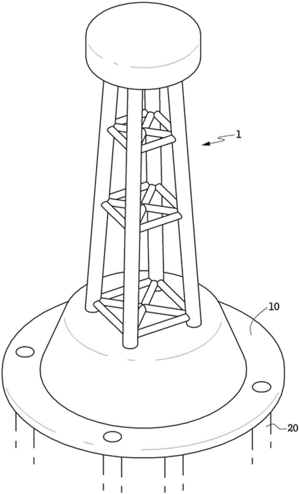
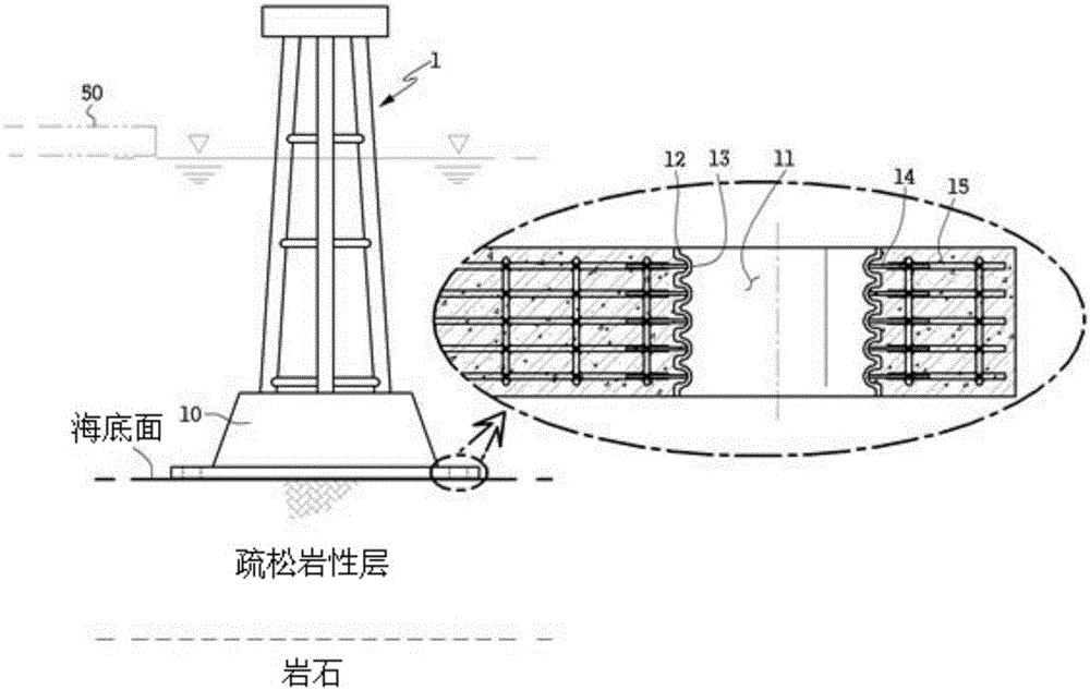
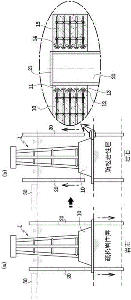
[0044] figure 1 To show a sectional view of an offshore support structure incorporating steel pipe piles of the present invention, Figures 2a to 2g is a drawing showing step by step the bonding method between the concrete base of the offshore support structure and the steel pipe piles of the present invention, image 3 It is a flow chart of the bonding method between the concrete base of the offshore support structure and the steel pipe piles of the present invention.

[0045] The present invention relates to a method of bonding steel pipe piles 20 to a concrete base 10 of an offsho...


PUM


Abstract

The present invention relates to a method to combine a concrete foundation of an offshore support structure and a steel pipe pile. The method comprises: (a) a step of positioning an offshore support structure having a concrete foundation on the seabed to be installed; (b) a step of inserting a steel pipe pile in an insertion hole of the concrete foundation and then cutting the steel pipe pile at the same level as the top level of the concrete foundation, at a predetermined height, or at a higher level; (c) a step of installing a form to close the top of the insertion hole of the concrete foundation such that grout to combine the concrete foundation and the steel pipe pile can be injected and cured; (d) a step of injecting the grout with an injection hose fitted while coming in contact with a grout injection port vertically penetrating the form; (e) a step of charging the grout in a separation space between the inner side surface of the insertion hole of the concrete foundation and the outer circumference of the inserted steel pipe pile while the grout circulates, or stopping the injection of the grout when the grout is discharged through a discharge hose fitted while being in contact with a grout outlet vertically penetrating the form; (f) a step of combining the concrete foundation and the steel pipe pile by curing the grout charged in the separation space between the inner side surface of the insertion hole of the concrete foundation and the outer circumference of the inserted steel pipe pile; and (g) a step of separating the form from the head of the steel pipe pile when the grout is completely cured. Thus, the present invention provides the convenience of construction and the stability of the support structure when the grout is charged between the concrete foundation and the steel pipe and the steel pipe pile is installed in the water.

Description

technical field [0001] The present invention relates to the bonding method between the concrete base of the offshore supporting structure and the steel pipe pile, more specifically relates to a kind of bonding method between the concrete base of the offshore supporting structure and the steel pipe pile. When combining with the steel pipe pile, it can be loaded and unloaded on the steel pipe pile cap by using a casting mold with an electromagnet, thereby filling the cement slurry between the concrete base and the steel pipe pile in water and installing the steel pipe pile It provides convenience for construction, and can obtain the stability of the supporting structure. Background technique [0002] Generally speaking, wind power, tidal power, etc., as new renewable energy, are rich in resources and continuously regenerated. They are distributed in a wide range of areas, and are environmentally friendly. In addition, there is no greenhouse gas emission due to power production...

Claims


Application Information

Patent Timeline
Patent Type & Authority Applications(China)
IPC IPC(8): E02D27/42E02D27/44
CPCE02D7/28E02D27/52
Inventor 崔真奥
Owner EPS ENG
Why Eureka
Try Eureka