
Composite cylinder type foundation with auxiliary piles added in later period

A cylindrical foundation and auxiliary pile technology, applied in the direction of foundation structure engineering, construction, etc., can solve the problems of high risk, overall structure damage, and high cost, and achieve the effects of improving efficiency, improving shear resistance and reducing production costs.

Inactive Publication Date: 2016-10-26
THE FRONTIER TECH RES INST OF TIANJIN UNIV
View PDF4 Cites 2 Cited by
  • Summary
  • Abstract
  • Description
  • Claims
  • Application Information

AI Technical Summary

Problems solved by technology

However, due to the differences in geological conditions in different wind fields, or even in different regions of the same wind field, the size and structure design of the cylindrical foundation are quite different
This greatly limits the batch and standardized production of the cylindrical foundation structure, and its design and manufacturing costs are relatively high
At the same time, since the design of the cylindrical foundation structure is basically determined by the geological conditions of the site, the relative floating and sinking conditions are less considered, which increases the construction cost of the cylindrical foundation to a certain extent
The most important thing is that since the composite cylindrical foundation is carried by a single structure, once the bearing capacity is insufficient, the overall structure will be damaged, and the risk is greater

Method used


Image

  • Composite cylinder type foundation with auxiliary piles added in later period
  • Composite cylinder type foundation with auxiliary piles added in later period

Examples


Embodiment

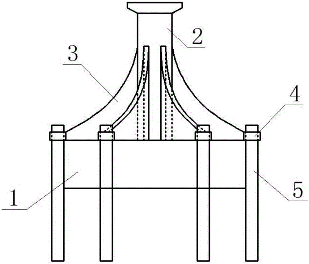
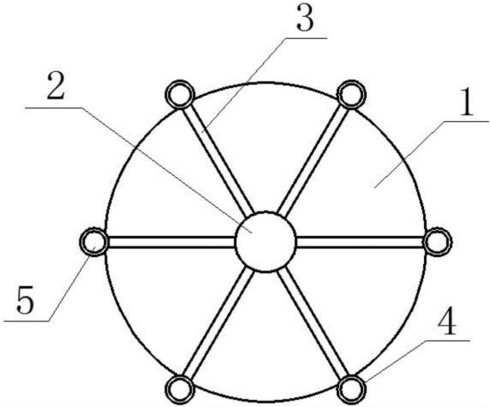
[0013] A composite cylindrical foundation with auxiliary piles added later, such as Figure 1-2 As shown, it is composed of a cylindrical foundation 1, a transition section 2, a reinforcing rib 3, an auxiliary pile fixing ring 4 and an auxiliary pile 5. The top cover of the cylindrical foundation 1 is a reinforced concrete structure, and the side wall is a steel structure; the cylindrical foundation 1 The center of the top cover is fixedly connected to the transition section 2; the transition section 2 is a steel structure with a diameter equal to the diameter of the lower end of the fan tower and connected to the fan tower through a flange; the transition section 2 and the top cover of the cylindrical foundation 1 are provided with six rings The reinforcing ribs 3 are evenly distributed radially; the reinforcing ribs 3 are steel structures, prefabricated with the transition section 2 and the top cover of the cylindrical foundation 1 as a unified whole; the outer bottom of the ...


PUM


Abstract

A composite cylinder type foundation with auxiliary piles added in the later period is composed of a cylindrical foundation body, a transition section, reinforcing ribs, auxiliary pile fixing ring sleeves and the auxiliary piles. The center of a cylindrical foundation body top cover is fixedly connected with the transition section. The transition section is connected with a fan tower cylinder through a flange. The reinforcing ribs are evenly distributed on the transition section and the cylindrical foundation body top cover annularly and radially. The reinforcing ribs, the transition section and the cylindrical foundation body top cover are prefabricated into a whole. The auxiliary pile ring sleeves are arranged at the bottom ends of the outer sides of the reinforcing ribs. After a cylindrical foundation structure is sunk, the auxiliary piles are driven into the cylindrical foundation structure, and the auxiliary piles are driven into a seabed through the auxiliary pile ring sleeves; and the auxiliary piles are fixedly connected with the auxiliary pile ring sleeves. The composite cylinder type foundation has the beneficial effects that due to the fact that auxiliary pile structures radially distributed on the edge of the composite cylinder type foundation have large pulling-resistant bearing capacity, the composite cylinder type foundation can resist the higher transverse load and the bending moment load; and by means of the cylinder type foundation, the standardized production and one-step type installation of the structure can be achieved, production and installation efficiency is improved greatly, and the production cost is lowered.

Description

technical field [0001] The invention relates to an offshore wind power foundation structure, in particular to a composite cylindrical foundation with auxiliary piles added later. Background technique [0002] In recent years, offshore wind power has developed rapidly as a green and clean renewable energy, and its market is growing rapidly at an annual rate of more than 40%. Offshore wind power has significant advantages such as good wind field quality, low turbulence, no occupation of cultivated land, and high annual utilization hours. However, the offshore environment is complex, the coupling effect of wind, wave and current on the foundation and tower structure is complicated, and the erosion and erosion of seawater on the foundation are obvious. At the same time, due to the complex offshore environment, the construction of the basic structure is more difficult, the cost is higher, and the later monitoring and maintenance costs are higher. Therefore, how to improve the b...

Claims


Application Information

Patent Timeline
Patent Type & Authority Applications(China)
IPC IPC(8): E02D27/42
CPCE02D27/425
Inventor 练继建刘润燕翔
Owner THE FRONTIER TECH RES INST OF TIANJIN UNIV
Learn More