Magnetic control lock, unlocking device and lock cylinder

An unlocking device and magnetically controlled lock technology, applied in the field of locks, can solve the problems of being unable to be used portablely, low anti-theft performance, low anti-theft security, etc. The realization method can be flexibly designed, the anti-theft safety performance can be improved, and the implementation methods are flexible and diverse Effect

Active Publication Date: 2018-03-16
ZHUHAI YOUTE SMART KITCHEN TECH CO LTD
View PDF5 Cites 0 Cited by
  • Summary
  • Abstract
  • Description
  • Claims
  • Application Information

AI Technical Summary

Problems solved by technology

Generally speaking, the lock cylinder of this type of lock is mainly realized by the structure of "mechanical pin + spring" or "leaf + spring". Locks are widely used in various industries and are easy to be opened technically. Theft accidents are not uncommon. Second, the protection is low. This type of lock uses a chip key inserted into the lock cylinder to unlock. There is a key channel in the lock cylinder, and there is no dustproof structure, in a harsh environment, if sand or other foreign matter enters the unlocking hole, it will cause the lock to fail
In this kind of magnetic control lock, a permanent magnet pin made of a permanent magnet is installed in the lock cylinder, and a permanent magnet is installed in the unlocking key. The principle of repelling each other and attracting each other of the same pole of the magnet is used to unlock the lock. However, there are still some problems. That is, the permanent magnet marble in the lock cylinder is easy to lose magnetism under the condition of high temperature and impact, which will cause the phenomenon that the lock cannot be opened, and there is also a key channel in the lock cylinder of this magnetic control lock. In harsh environments, it is easy to enter sand. Dust or other foreign matter, and the iron core of the permanent magnet is easy to absorb foreign matter, so it is very easy to be disturbed by foreign matter and cause the phenomenon that the lock cannot be unlocked
[0004] On the basis of the above-mentioned problems, another improved lock has been proposed in the prior art, that is, a further improvement is made on the basis of the above-mentioned magnetic control lock, and the permanent magnet in the lock cylinder that is easy to lose magnetism is replaced with a magnetic control lock based on a guide. The magnetically conductive pin made of magnetic material can avoid the problem that the permanent magnet pin is easy to lose magnetism, but there are still some problems, that is, this kind of magnetic control lock made of magnetic pin has a key channel in the lock cylinder. , and there is no dust-proof structure, sand or other foreign matter is still easy to enter the unlocking hole, which will also cause the lock to fail
In addition, this kind of magnetic control lock made of magnetic-conducting marbles generally has weak suction. In order to increase its suction, the warhead of the magnetic-conducting marble is generally exposed, so that anyone can know the position of the bullet. Any magnetic object It can be absorbed, and the anti-theft security is not high; or, based on the security considerations of anti-theft, it is also possible to design the magnetic-conducting pin to be completely hidden inside the lock cylinder, but in this way, the key does not have a high suction force on the magnetic-conducting pin , it is not easy to realize unlocking, and if it is necessary to increase the suction force of the key to the magnetically conductive marble, the volume of the magnet in the key can only be greatly increased. In this way, the volume of the key will be greatly increased, and the purpose of portable use cannot be achieved, and Even in this way, the lockset has only one locking method, and its anti-theft security is not high.
[0005] In addition, in view of the problem that the key channel in the lock cylinder cannot be dust-proof in the prior art, some technicians also consider designing a dust-proof structure in the lock cylinder. However, in view of the small space and special structure inside the lock cylinder, designing Dust-proof structure is really difficult to achieve
[0006] Therefore, there is currently no suitable lockset to solve the problems of poor dustproof and anti-theft effects of existing locksets, and existing locksets still need to be improved in terms of dustproof, anti-theft and portable use.

Method used


Image

  • Magnetic control lock, unlocking device and lock cylinder
  • Magnetic control lock, unlocking device and lock cylinder
  • Magnetic control lock, unlocking device and lock cylinder

Examples


Embodiment 1

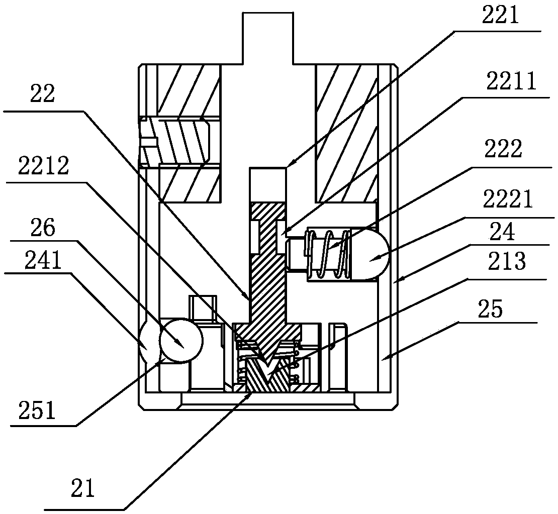
[0083] Refer to the attached Figure 7 And attached Figure 8 shown, among them, attached Figure 7 It is a schematic diagram of the cross-sectional structure of the first embodiment of the present invention in the locked state, with Figure 8 It is a schematic diagram of the cross-sectional structure of the first embodiment of the present invention in the unlocked state. As shown in the figure, in the first embodiment, the electromagnetic device 12 adopts the figure 2 The same implementation method as in , will not be repeated here. The second magnetically conductive part 21 in the lock core 2 adopts the same realization method as the first magnetically conductive part 121, that is, the second magnetically conductive part 21 is a hollow first magnetically conductive cylinder with one end closed and one end open and placed on the It is composed of a second magnetically permeable cylinder in the middle of the hollow first magnetically permeable cylinder, one end of the seco...

Embodiment 2

[0088] Refer to the attached Figure 9 And attached Figure 10 shown, among them, attached Figure 9 It is a schematic diagram of the cross-sectional structure of the second embodiment of the present invention under the locked state, with Figure 10It is a schematic cross-sectional structure diagram of the second embodiment of the present invention in an unlocked state. As shown in the figure, in the second embodiment, the first magnetically conductive member 121 is composed of an L-shaped magnetically conductive shell and a magnetically conductive column, wherein, The magnetically permeable column is arranged flush with the vertical section of the L-shaped magnetically permeable housing, and one end of the magnetically permeable column is connected to the horizontal section of the L-shaped magnetically permeable housing, and the coil 122 is wound on the magnetically permeable column.

[0089] The second magnetically permeable component 21 is divided into two parts, a first ...

Embodiment 3

[0093] Refer to the attached Figure 11 And attached Figure 12 shown, among them, attached Figure 11 It is a schematic diagram of the cross-sectional structure of the third embodiment of the present invention in the locked state, with Figure 12 It is a schematic cross-sectional structure diagram of the third embodiment of the present invention in an unlocked state. As shown in the figure, in the third embodiment, the first magnetically conductive member 121 is a hollow cylinder with one end closed and one end open, and the coil 122 is wound around the sleeve connected to the closed end of the first magnetic permeable component 121 . The second magnetically permeable component 21 is divided into two parts, the two parts are set independently, and one end of the two parts can be aligned with the first magnetically permeable component 121 respectively.

[0094] The difference from the previous two embodiments is that in the first embodiment and the second embodiment, the in...


PUM


Abstract

The invention provides a magnetic-control lock. The magnetic-control lock comprises an unlocking device and a lock cylinder. An electromagnetic device is arranged in the unlocking device. The electromagnetic device comprises a coil and a first magnetism-conducting component. A second magnetism-conducting component and at least one magnetic-control locking component capable of moving based on magnetic force are arranged in the lock cylinder. When the unlocking device and the lock cylinder are in butt joint and the first magnetism-conducting component and the second magnetism-conducting component are aligned, the electromagnetic device in the unlocking device is powered on, the electromagnetic device in the unlocking device and the second magnetism-conducting component in the lock cylinder form an electromagnetic circuit jointly, the magnetic-control locking component moves under the effect of the electromagnetic circuit, and thus unlocking of the lock cylinder can be achieved. According to the magnetic-control lock, a key channel is omitted, dust can be effectively prevented from entering the lock cylinder, the dust-proof function of the lock is greatly improved, and the anti-theft performance of the lock is also improved; and in addition, the size of the unlocking device is reduced while the suction force to the locking component is increased, and the unlocking device is easier to carry and use accordingly.

Description

technical field [0001] The invention relates to the field of locks, in particular to a magnetic control lock, an unlocking device and a lock cylinder. Background technique [0002] In the prior art, based on the need for anti-theft in the general field or preventing accidents in the industrial field, it is a common locking method to lock potential dangerous points such as doors, cabinets, equipment, or operating mechanisms with locks. Generally speaking, the lock cylinder of this type of lock is mainly realized by the structure of "mechanical pin + spring" or "leaf + spring". Locks are widely used in various industries and are easy to be opened technically. Theft accidents are not uncommon. Second, the protection is low. This type of lock uses a chip key inserted into the lock cylinder to unlock. There is a key channel in the lock cylinder, and there is no dustproof In harsh environments, dust or other foreign matter entering the unlocking hole will result in failure to unl...

Claims


Application Information

Patent Timeline
Patent Type & Authority Patents(China)
IPC IPC(8): E05B47/00E05B17/00E05B15/00E05B15/16E05B49/02
CPCE05B15/00E05B15/16E05B17/002E05B47/0001E05B49/00
Inventor 黄建东郭正柔周子敬文琪
Owner ZHUHAI YOUTE SMART KITCHEN TECH CO LTD
Why Eureka
Try Eureka