
Oil head of Kaplan turbine and Kaplan turbine with oil head

The technology of one type of water turbine and oil receiver is applied in the direction of machine/engine, hydroelectric power generation, mechanical equipment, etc. It can solve the problems of burning tiles, floating tile blocking, etc., so as to reduce oil leakage, prolong the service life and simplify the working principle. Effect

Inactive Publication Date: 2016-10-26
湖南云箭科技有限公司
View PDF9 Cites 6 Cited by
  • Summary
  • Abstract
  • Description
  • Claims
  • Application Information

AI Technical Summary

Problems solved by technology

Although the technical solution has been improved to a certain extent, it may still cause floating tile jamming and tile burning accidents

Method used


Image

  • Oil head of Kaplan turbine and Kaplan turbine with oil head
  • Oil head of Kaplan turbine and Kaplan turbine with oil head

Examples


Embodiment Construction

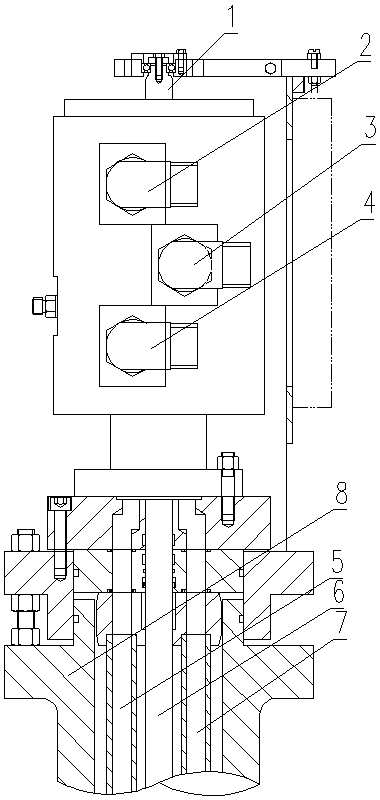
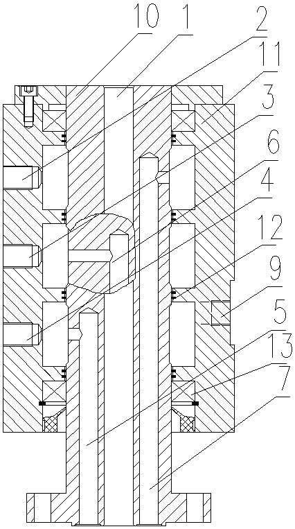
[0017] The specific implementation manners of the present invention will be further described in detail below in conjunction with the accompanying drawings.

[0018] Such as figure 1 and 2 The rotary paddle turbine and its oil receiver shown include a moving ring 10 detachably connected to the main shaft 8; a static ring 11 rotatably connected to the moving ring 10 through two bearings 13; a first oil pipe 2 connected to the static ring 11 , the second oil pipe 3, the third oil pipe 4; between the moving ring 10 and the static ring 11, the first oil chamber, the second oil chamber, the second oil chamber, which communicate with the first oil pipe 2, the second oil pipe 3, and the third oil pipe 4 respectively The third oil chamber; the first operating oil pipe 7, the second operating oil pipe 6, and the third operating oil pipe 5, which are respectively connected to the first oil chamber, the second oil chamber, and the third oil chamber in the moving ring 10; the first opera...


PUM


Abstract

The invention provides an oil head of a Kaplan turbine and the Kaplan turbine with the oil head. The oil head comprises a movable ring (10) connected with a main shaft (8), a fixed ring (11) rotationally connected with the movable ring (10) through two bearings (13), a first oil pipe (2), a second oil pipe (3), a third oil pipe (4), a first oil cavity, a second oil cavity, a third oil cavity, a first operation oil pipe (7), a second operation oil pipe (6) and a third operation oil pipe (5). The first oil pipe (2), the second oil pipe (3) and the third oil pipe (4) are connected with the fixed ring (11). The first oil cavity, the second oil cavity and the third oil cavity are located between the movable ring (10) and the fixed ring (11) and communicate with the first oil pipe (2), the second oil pipe (3) and the third oil pipe (4) correspondingly. The first operation oil pipe (7), the second operation oil pipe (6) and the third operation oil pipe (5) are located in the movable ring (10) and communicate with the first oil cavity, the second oil cavity and the third oil cavity correspondingly. The first operation oil pipe (7), the second operation oil pipe (6) and the third operation oil pipe (5) communicate with a closing cavity, a pressure keeping cavity and an opening cavity of the oil head correspondingly.

Description

technical field [0001] The invention relates to the technical field of water turbines, in particular to a paddle type water turbine and an oil receiver thereof. Background technique [0002] The oil receiver is an important part of the turbine. It is a conversion device that transmits the oil source through the operating oil pipe through the fixed casing. It is used to continuously inject the high-pressure oil from the governor into the runner through the operating oil pipe. Two chambers of the piston in the assembly. The two cavities of the operating oil pipe return oil to each other, and the pressure oil is used to operate the piston mechanism to adjust the rotation of the blades of the turbine, so as to achieve the purpose of adjusting the load of the unit and starting and stopping. The oil receiver is generally installed on the generator floor, and the guide shoe between the oil receiver body and the operating oil pipe adopts a fixed shoe structure. Since the length of ...

Claims


Application Information

Patent Timeline
IPC IPC(8): F03B11/00F03B15/00
CPCF03B11/00F03B11/006F03B15/00Y02E10/20
Inventor 解再益陈可建
Owner 湖南云箭科技有限公司
Features
  • Generate Ideas
  • Intellectual Property
  • Life Sciences
  • Materials
  • Tech Scout
  • Unparalleled Data Quality
  • Higher Quality Content
  • 60% Fewer Hallucinations
Learn More