Pyrolysis fuel gas and air rapid mixing device

A technology of air and gas, which is applied in combustion chambers, combustion methods, combustion equipment, etc., and can solve problems such as rapid mixing of pyrolysis gas and air

Active Publication Date: 2016-10-26
HARBIN ENG UNIV
View PDF4 Cites 6 Cited by
  • Summary
  • Abstract
  • Description
  • Claims
  • Application Information

AI Technical Summary

Problems solved by technology

However, it is still a big problem to be solved whether it is possible to ensure the rapid mixing of pyrolysis gas and air so that the pyrolysis gas can be burned in lean combustion areas.

Method used


Image

  • Pyrolysis fuel gas and air rapid mixing device
  • Pyrolysis fuel gas and air rapid mixing device
  • Pyrolysis fuel gas and air rapid mixing device

Examples


Embodiment Construction

[0017] Hereinafter, the present invention will be described in more detail with examples in conjunction with the accompanying drawings:

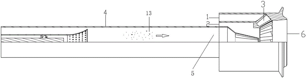
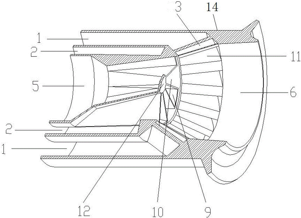
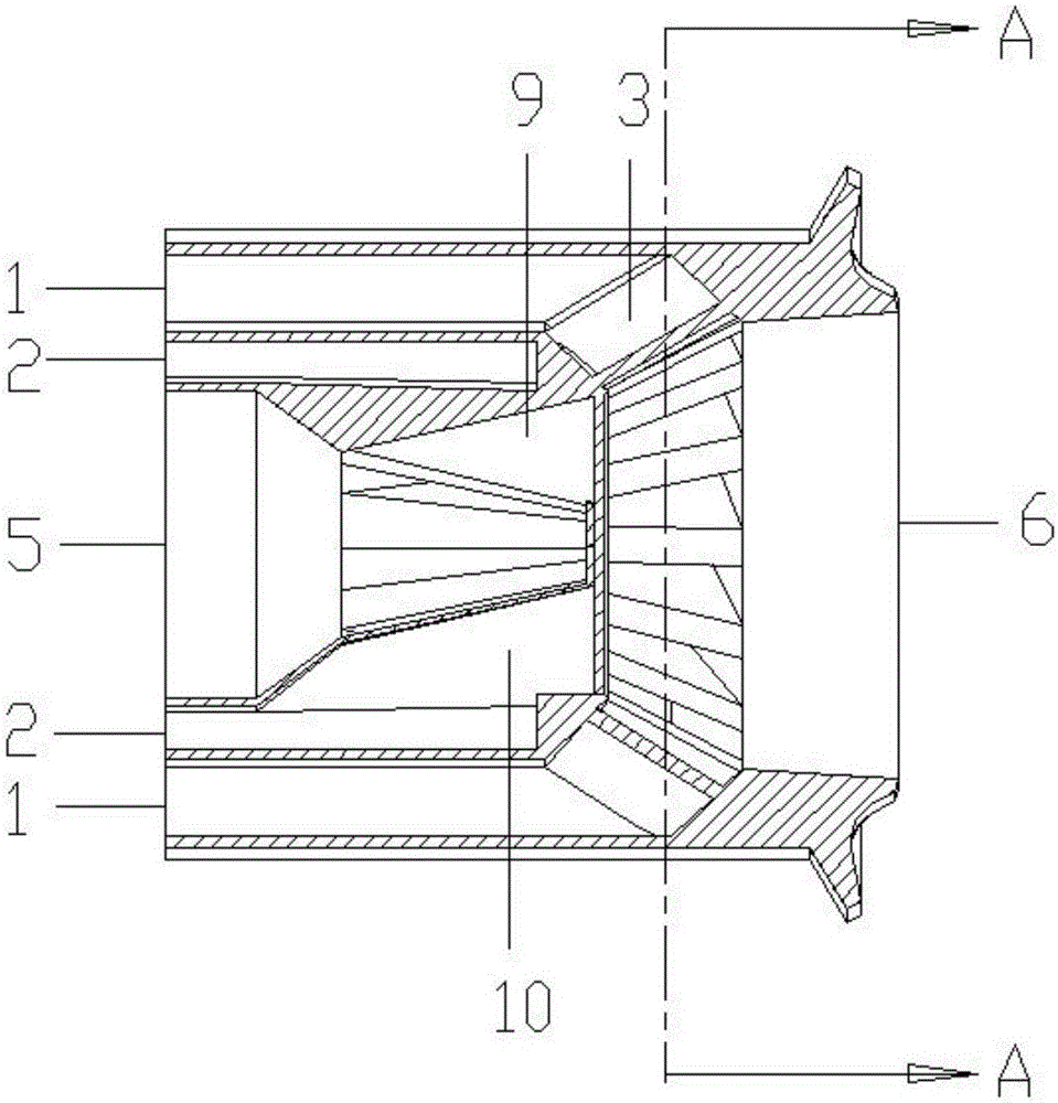
[0018] Combine Figure 1-4 The pyrolysis gas-air rapid mixing device of the present invention includes a swirler air inlet flow channel 1, a lobe mixing air flow channel 2, an oblique radial flow channel 3 installed with swirl blades, and an inner flow channel of the lobe mixing structure Cracking gas inlet 5, cracking gas-air blending gas outlet 6, swirling blade 7, lobe blender 8, lobe convex structure 9 is also a lobe blending structure internal flow channel cracking gas outlet, lobe concave structure 10 It is also the air outlet of the outer flow channel of the lobe blending structure, the oblique radial flow channel outlet 11 with the swirling blades, the closed structure 12 of the center flow channel of the lobe blending structure, the cyclone 14, the device and the rich oil pyrolysis combustion Room 4 installation structure such as figu...


PUM


Abstract

The invention aims at providing a pyrolysis fuel gas and air rapid mixing device. The pyrolysis fuel gas and air rapid mixing device comprises an outer shell, an inner shell and a lobe mixer, wherein the inner shell is arranged in the outer shell; a hydrocyclone air inlet passage is formed between the inner shell and the outer shell; the lobe mixer comprises a lobe mixing structure inner passage wall, lobe convex structures and lobe concave structures; the lobe convex structures and the lobe concave structures are arranged alternately to form an annular structure; the lobe mixing structure inner passage wall is connected with the annular structure; a lobe mixing structure inner passage pyrolysis fuel gas inlet communicating with a rich oil pyrolysis combustion chamber is formed in the lobe mixing structure inner passage wall; the lobe mixer is arranged in the inner shell, and a lobe mixing air passage is formed between the lobe mixing structure inner passage wall and the inner shell; an inclined radial runner provided with cyclone blades is installed at an outlet of the lobe mixer; and a pyrolysis fuel gas and air mixing gas outlet is arranged at an outlet of the inclined radial runner. The pyrolysis fuel gas and air rapid mixing device can complete rapid mixing of pyrolysis fuel gas and air, and lowers generation of lean burning area NOx.

Description

Technical field [0001] The invention relates to a gas turbine combustor, in particular to a blending device for the gas turbine combustor. Background technique [0002] Low-emission combustion technology has gradually become one of the central issues of engine combustion technology. In response to this problem, such as staged combustion, rich-quench-lean (RQL), double-rotation premixed swirl (TAPS), lean Mixed pre-evaporation (LPP), lean oil multiple point injection (LDI) and other technologies. These technologies have been able to meet the current ICAO emissions requirements. RQL combustion technology is the best among many low-emission combustion technologies, and the combustion in the rich oil zone is an important part of its combustion technology realization. In the fuel-rich combustion section, fuel and air are mixed and burned at a high equivalent ratio (1.4-1.8) to produce a large number of highly active groups, which lays the foundation for subsequent quenching and lean...

Claims


Application Information

Patent Timeline
Patent Type & Authority Applications(China)
IPC IPC(8): F23R3/28
CPCF23R3/286
Inventor 郑洪涛邵志强张国强唐胜杨家龙李智明杨洪磊杨仁
Owner HARBIN ENG UNIV
Why Eureka
Try Eureka