A damper adjustment mechanism for a gas cooker

A damper adjustment and gas cooker technology, which is applied in the field of household kitchen utensils, can solve the problems of large air ejection resistance, insufficient combustion, nozzle clogging, etc., and achieve the goals of improving combustion efficiency and thermal efficiency, improving insufficient ejection, and reducing smoke emissions Effect

Active Publication Date: 2022-03-18
NINGBO FOTILE KITCHEN WARE CO LTD
View PDF13 Cites 0 Cited by
  • Summary
  • Abstract
  • Description
  • Claims
  • Application Information

AI Technical Summary

Problems solved by technology

Among them, the air nozzle is located inside the mixing cylinder, and the size of the damper is controlled by an air regulating mechanism. The main disadvantages are as follows: 1. The nozzle is located inside the mixing cylinder, and the heat dissipation is not good. The heat of the mixing cylinder is easily transferred to the nozzle. During the cooking process , the load of the nozzle is easily affected; 2. The nozzle is located inside the mixing cylinder. During the long-term cooking process, when the inner ring has soup entering the mixing cylinder, it is easy to cause the nozzle to be blocked (although the soup can flow from the through hole connected to the mixing cylinder and the air) out, but when the opening of the air regulating mechanism is small or large, it is still easy to cause blockage); 3. The ability of the nozzle to inject air needs to be strengthened, and the existing structure has a greater resistance to air injection; 4. This damper The adaptability of the adjustment method is poor. When the damper is closed very small, the air cannot be supplied, resulting in insufficient combustion

Method used


Image

  • A damper adjustment mechanism for a gas cooker
  • A damper adjustment mechanism for a gas cooker
  • A damper adjustment mechanism for a gas cooker

Examples


Embodiment 1

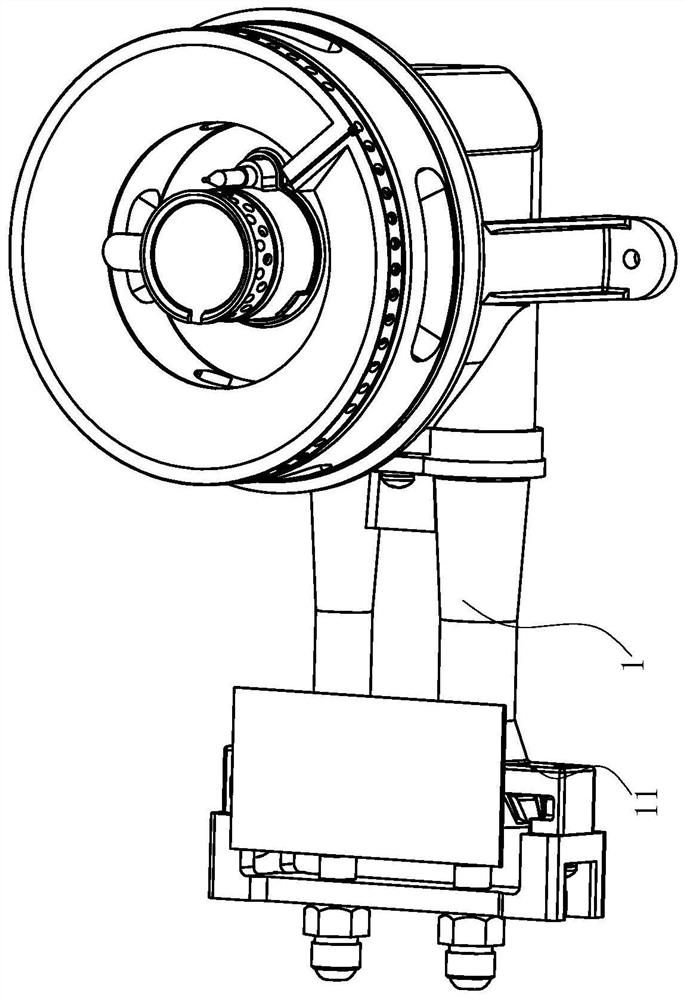
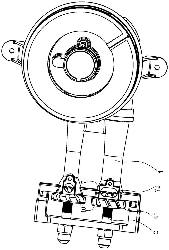
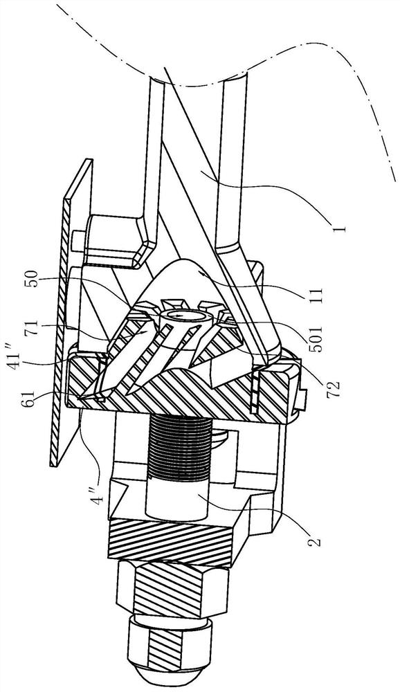
[0046] Such as Figure 1-10 As shown, it is the best embodiment of the present invention. In this embodiment, the damper adjustment mechanism for the gas cooker includes an injection pipe 1, a nozzle seat 2 and a nozzle 3 installed on the nozzle seat 2. The nozzle of the nozzle 3 faces The air inlet end 11 of the ejection pipe 1 also includes an air guide member installed on the nozzle seat 2, the air guide member includes a body, the center of the body has a central hole 50 for the nozzle 3 to extend into, and the body also has at least Two guide parts arranged around the central hole 50, the interval between adjacent guide parts forms a primary air channel 40 "for guiding the primary air. Due to the primary air channel 40", the air guide can be simply The central hole 50 is sleeved outside the nozzle 3 or the nozzle seat 2, for example, the two are screwed together, so that the air guide can be positioned and the position between the air guide and the nozzle 3 can be adjuste...

Embodiment 2

[0051] Different from the structure of Embodiment 1, the structure of the air guide can also be as follows: the air guide includes a plate body 5', the central hole 50 is arranged at the center of the plate body 5', and the guide part is arranged on the plate body 5'. Peripheral locations other than the central hole 50 . Wherein, the guide part is a cantilever-type raised strip 4', and the adjacent cantilever-shaped raised strip 4' forms a primary air passage 40', and the primary air passage 40' includes an air outlet end 401' adjacent to the central hole 50 and an air outlet end far away from the center. The inlet end 402' of the hole 50, the diameter of the inlet end 402' is larger than the diameter of the outlet end 401', so that the primary air in the primary air passage can be accelerated after it enters, and the swing arm type convex strip 4' includes a The outer end 41' of 50 and the inner end 42' adjacent to the central hole 50, the width of the outer end 41' of the ca...

Embodiment 3

[0053] Different from the adjusting part 6 with the plate body 5' in Embodiments 1 and 2, the air guiding part in this embodiment is in the shape of a circular platform 5. In order to enhance the ability of the air guiding part to guide the primary air, the air guiding part is gradually moving toward the air guiding part. The air inlet end 11 of the jet tube 1 is in the shape of a circular platform 5, and the guide part is a rib 4, which is arranged on the side wall of the air guide. The interval between adjacent guide parts forms a primary air for guiding the primary air. The channel 40 , the primary air channel 40 includes an air outlet 401 adjacent to the central hole 50 and an inlet 402 away from the central hole 50 , the diameter of the inlet 402 is larger than that of the outlet 401 . The rib 4 includes an outer end 41 far away from the air inlet end 11 of the ejector tube 1, and an inner end 42 adjacent to the air inlet end 11 of the ejector tube 1. The rib 4 gradually p...


PUM


Abstract

The invention relates to a damper adjustment mechanism for a gas cooker, which includes an injection pipe, a nozzle seat and a nozzle installed on the nozzle seat, the nozzle of the nozzle faces the air inlet end of the injection pipe, and is characterized in that: It includes an air guide installed on the nozzle seat, and the air guide can move relative to the air inlet end of the ejector tube along the axis of the ejector tube; the air guide includes a body, and the center of the body has a The central hole in which the nozzles are aligned, the body also has at least two guide parts arranged at intervals around the central hole along the circumferential direction, the interval between adjacent guide parts forms a primary air channel for guiding primary air, which is similar to the existing Compared with the prior art, the advantage of the present invention is to provide a new air guide, the center of the air guide is gas, and the guide parts are arranged at intervals along the circumference of the air guide body, which can realize the primary air to rotate around the gas , and then promote the rapid mixing of gas and primary air before the gas inlet end of the injection tube.

Description

technical field [0001] The invention relates to the field of household kitchen utensils, in particular to a damper adjustment mechanism for a gas cooker. Background technique [0002] Most of the existing cooker burners on the market are atmospheric burners, which need to pre-mix part of the primary air, which requires a damper primary air passage size adjustment device to adjust the amount of pre-mixed primary air required. At present, there are two most common methods: one is to change the effective circulation area of ​​the primary air suction port by rotating the air regulating plate and moving the air regulating plate back and forth, thereby adjusting the suction volume of the primary air; this form of air regulating When the air regulating plate reaches the ejection tube, it continues to rotate in the direction of the ejecting pipe, which will cause the air regulating plate to be stuck and not easy to rotate; the second is that the air regulating plate is fixed on the ...

Claims


Application Information

Patent Timeline
Patent Type & Authority Patents(China)
IPC IPC(8): F23D14/04F23D14/46F23D14/48F23D14/64F23D14/70F24C3/08
CPCF23D14/04F23D14/46F23D14/48F23D14/64F23D14/70F24C3/085
Inventor 胡潇柯情
Owner NINGBO FOTILE KITCHEN WARE CO LTD
Why Eureka
Try Eureka