
Motor recovery detection device

A detection device and detection platform technology, applied in the direction of measuring devices, optical devices, instruments, etc., can solve problems such as troublesome operation, injury to the tester, unscientific and rationality, etc., to achieve convenient manufacturing and use, and reduce Operational intensity and the effect of guaranteeing the detection effect

Active Publication Date: 2018-08-28
CHANGSHU INSTITUTE OF TECHNOLOGY
View PDF10 Cites 0 Cited by
  • Summary
  • Abstract
  • Description
  • Claims
  • Application Information

AI Technical Summary

Problems solved by technology

[0004] There are at least the following technical problems in the above method of determining whether the motor is recyclable by looking, listening and touching with the help of comprehensive judgment: First, since all links are carried out based on human subjective feelings, the results are often determined by human factors. Different, it is unscientific and rational; second, because all the processes are all carried out step by step with human participation, so the efficiency is low; third, the operation is troublesome, because the motor needs to be fixed reasonably when testing the motor; other Fourth, there is a loss of safety, and there is a risk of injury to the tester
[0009] In view of the fact that the motor detection device in the prior art cannot adapt to the detection of motors of different specifications to be recycled, and in view of the fact that the motor detection device belongs to non-standard detection equipment, non-standard detection equipment is often determined by the detection department according to the target product to be detected. Tailor-made design and manufacture are based on such factors. In the current published patents and non-patent literature, there is no technical inspiration for a special detection device suitable for the detection of recycled motors.

Method used


Image

  • Motor recovery detection device

Examples


Embodiment Construction

[0023] In order to more clearly understand the technical essence and beneficial effects of the present invention, the applicant will describe in detail below the manner of the embodiment, but the description of the embodiment is not a limitation to the solution of the present invention, and any design made according to the concept of the present invention is only All equivalent transformations that are formal rather than substantive should be regarded as the scope of the technical solution of the present invention.

[0024] In the following descriptions, all concepts related to directionality or orientation of up, down, left, right, front and back are based on figure 1 The position shown is a reference, so it cannot be understood as a special limitation on the technical solution provided by the present invention.

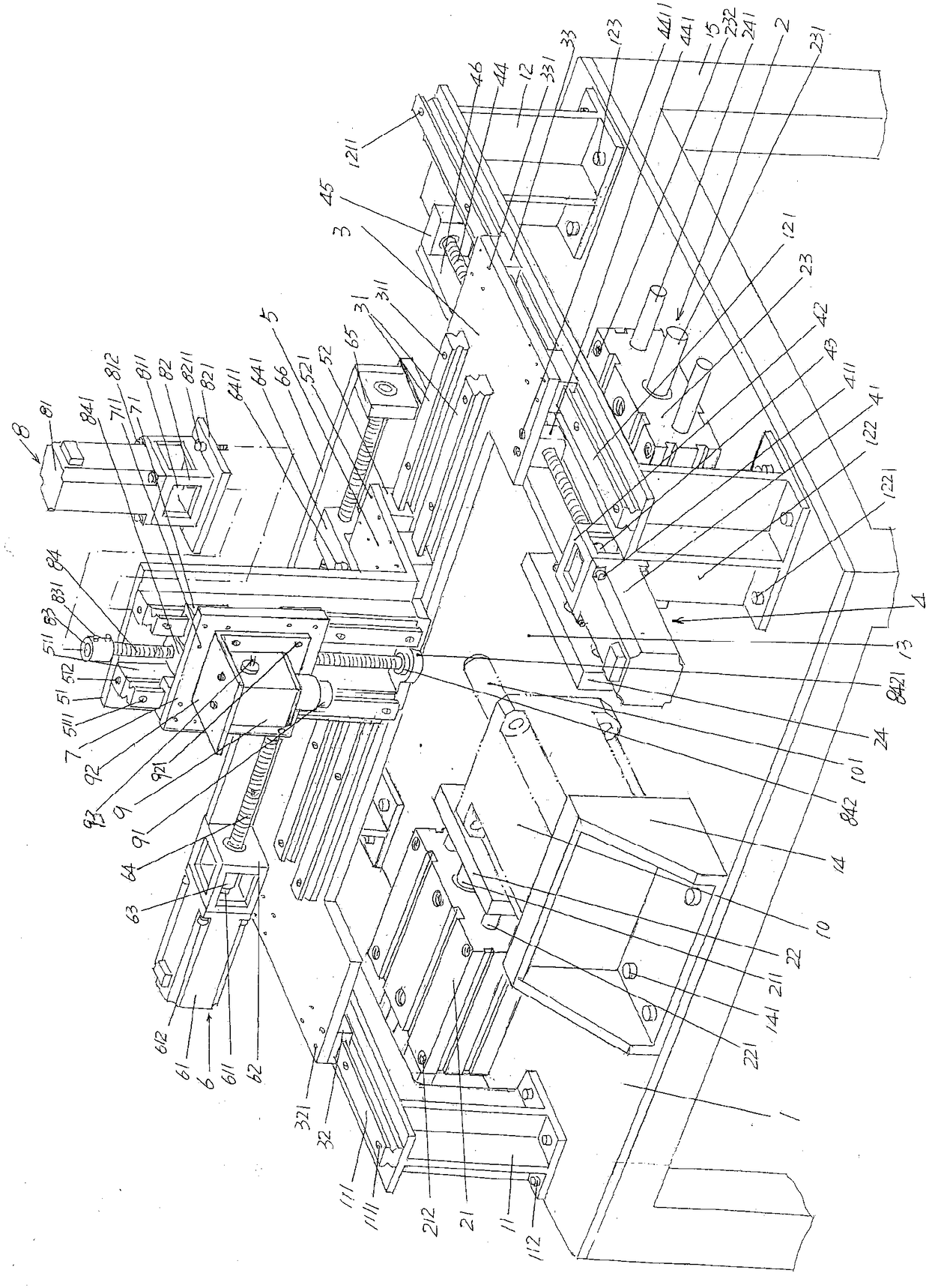
[0025] See figure 1 , shows a detection platform 1, the detection platform 1 is supported on the floor of the detection site by a platform leg 15 at each of its fo...


PUM


Abstract

The invention discloses a motor recovery detection device, which comprises a detection platform, a to-be-detected motor clamping mechanism, a forward-backward movement platform, a forward-backward movement platform driving mechanism, a left-right movement platform, a left-right movement platform driving mechanism, a camera vertical movement platform, a camera vertical movement platform driving mechanism and a camera, wherein the left end of the detection platform is provided with a left guide rail and the right end is provided with a right guide rail; the to-be-detected motor clamping mechanism is arranged on the detection platform; the left end of the forward-backward movement platform is matched with the left guide rail, the right end is matched with the right guide rail, and the middle is provided with a left-right movement platform guide rail; the forward-backward movement platform driving mechanism is arranged on a right guide rail support and is matched with the right end of the forward-backward movement platform; the left-right movement platform is provided with a vertical guide rail fixing plate, and a vertical guide rail is arranged at the front side of the vertical guide rail fixing plate; the left-right movement platform driving mechanism is fixed with the forward-backward movement platform and is connected with the left-right movement platform; the camera vertical movement platform is matched with a vertical guide rail; the camera vertical movement platform driving mechanism is arranged at the top of the vertical guide rail and matched with the camera vertical movement platform; and the camera is fixed at the front side of the camera vertical movement platform, and the camera lens faces downwardly. Good generality is reflected, the work intensity is lessened, ideal detection effects are ensured, manufacturing and use are facilitated, and the motor recovery detection device is ensured to be economic and cheap.

Description

technical field [0001] The invention belongs to the technical field of detection machinery, and in particular relates to a motor recycling detection device. Background technique [0002] All kinds of scrapped electromechanical equipment with power mechanism and various machinery are usually equipped with motors. Since these equipment and machinery have a high probability of being intact as the motor of the structural system of the power mechanism when they are scrapped, if no distinction is made If it is discarded indiscriminately, it will undoubtedly cause a waste of resources. However, if the motor is reused blindly, frequent failures will occur again. Therefore, the problem of how to find a reasonable balance between saving resources and rationally utilizing the motors removed from waste equipment has long puzzled waste equipment recycling departments. [0003] At present, the motors removed from waste equipment are usually judged by looking, hearing and touching to det...

Claims


Application Information

Patent Timeline
Patent Type & Authority Patents(China)
IPC IPC(8): G01B11/00
CPCG01B11/00
Inventor 刘建花马文斌戴国洪周自强刘忠
Owner CHANGSHU INSTITUTE OF TECHNOLOGY
Learn More