Apparatus for measuring fluorescence lifetime

A fluorescence lifetime and measurement device technology, applied in fluorescence/phosphorescence, material excitation analysis, etc., can solve the problems of inability to measure the doping concentration of solid samples, the inability to measure the spatial distribution of doping concentration, and the limitation of disk thickness

Active Publication Date: 2016-10-26
ELECTRONICS & TELECOMM RES INST
View PDF5 Cites 6 Cited by
  • Summary
  • Abstract
  • Description
  • Claims
  • Application Information

AI Technical Summary

Problems solved by technology

Therefore, ICP-MS cannot measure the doping concentration of solid samples in the shape of rods or disks, and cannot measure the spatial distribution of doping concentration
[0006] Moreover, although optical absorption spectroscopy is capable of measuring the concentration of a solid sample in the shape of a disk, in order to minimize the scattering and diffuse reflection (diffuse reflectance) of light entering the sample, both surfaces of the disk must be processed to have an Surfaces of optical quality less than λ / 5, and the concentration of rod-shaped solid samples cannot be measured by optical absorption spectroscopy
Also, since the spectrophotometer can perform accurate measurement only when the optical density (OD) is equal to or less than 4, the measurable disc thickness is limited (generally, a disc having a thickness equal to or less than about 5 mm is used, But it changes according to the type of rare earth ion and doping concentration)

Method used


Image

  • Apparatus for measuring fluorescence lifetime
  • Apparatus for measuring fluorescence lifetime
  • Apparatus for measuring fluorescence lifetime

Examples


Embodiment Construction

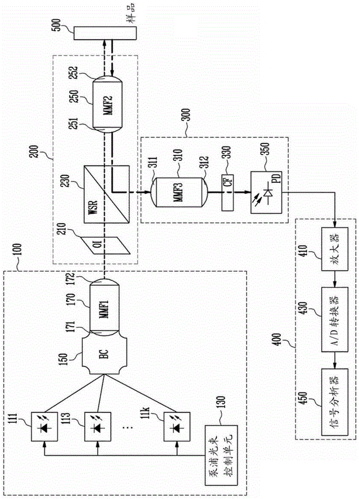
[0015] Hereinafter, embodiments will be described in more detail with reference to the accompanying drawings. Embodiments are described herein with reference to cross-section illustrations that are schematic illustrations of embodiments (and intermediate structures). As such, deviations from the illustrated shapes are to be expected as a result, for example, of manufacturing techniques and / or tolerances. Thus, embodiments should not be construed as limited to the particular shapes of regions illustrated herein but may be to include deviations in shapes that result, for example, from manufacturing. In the drawings, the lengths and dimensions of layers and regions may be exaggerated for clarity. The same reference numerals in the figures denote the same elements.

[0016] Terms such as 'first' and 'second' may be used to describe various components, but they should not limit the various components. Those terms are used only for the purpose of distinguishing one component from...


PUM

PropertyMeasurementUnit
thicknessaaaaaaaaaa

Abstract

Provided herein is an apparatus for measuring fluorescence lifetime that can easily and accurately measure a fluorescence lifetime without destroying an object to be measured. The fluorescence lifetime measurement apparatus comprises a plurality of pump beam sources, a pump beam combiner, a first multimode optical fiber, a second multimode optical fiber and a third multimode optical fiber, an optical isolator, a wavelength selective reflective filter, a cutoff filter, and a photodiode.

Description

technical field [0001] Various embodiments of the present disclosure relate to devices for measuring fluorescence lifetime. Background technique [0002] A high-power output solid-state laser uses a single crystal doped with a small amount of rare earth ions and manufactured in a rod or disk shape as a laser oscillation medium. Here, the doping concentration and fluorescence lifetime of the rare earth ions in the laser oscillation medium are core material properties of the medium that determine the oscillation characteristics of the laser. [0003] Typically, fluorescence lifetime is determined by measuring the decay kinetics of fluorescence intensity by time-resolved fluorescence spectroscopy. However, conventional fluorescence lifetime measurement uses a monochromator for selecting a certain wavelength of fluorescence, so there are limitations in integrating and minimizing the measurement equipment. [0004] Methods for analyzing the doping concentration include a method...

Claims


Application Information

Patent Timeline
Patent Type & Authority Applications(China)
IPC IPC(8): G01N21/64
Inventor 周正振
Owner ELECTRONICS & TELECOMM RES INST
Why Eureka
Try Eureka