
Unmanned plane having anaesthesia function and remote tracking system

An unmanned aerial vehicle and functional technology, applied in the field of remote tracking system, can solve the problems of no infrared system and anesthesia device, and can not be used in large-scale wildlife parks, etc., and achieve the effect of high degree of intelligence and easy control.

Inactive Publication Date: 2016-10-26
佛山杰致信息科技有限公司
View PDF8 Cites 11 Cited by
  • Summary
  • Abstract
  • Description
  • Claims
  • Application Information

AI Technical Summary

Problems solved by technology

The UAV, driven by multi-rotors, can detect insect pests and spray pesticides in agriculture and forestry. However, since this UAV does not have an infrared system and anesthesia device, it cannot be used in large-scale wildlife parks or livestock farms. , to anesthetize the tracker

Method used


Image

  • Unmanned plane having anaesthesia function and remote tracking system
  • Unmanned plane having anaesthesia function and remote tracking system

Examples


Embodiment 1

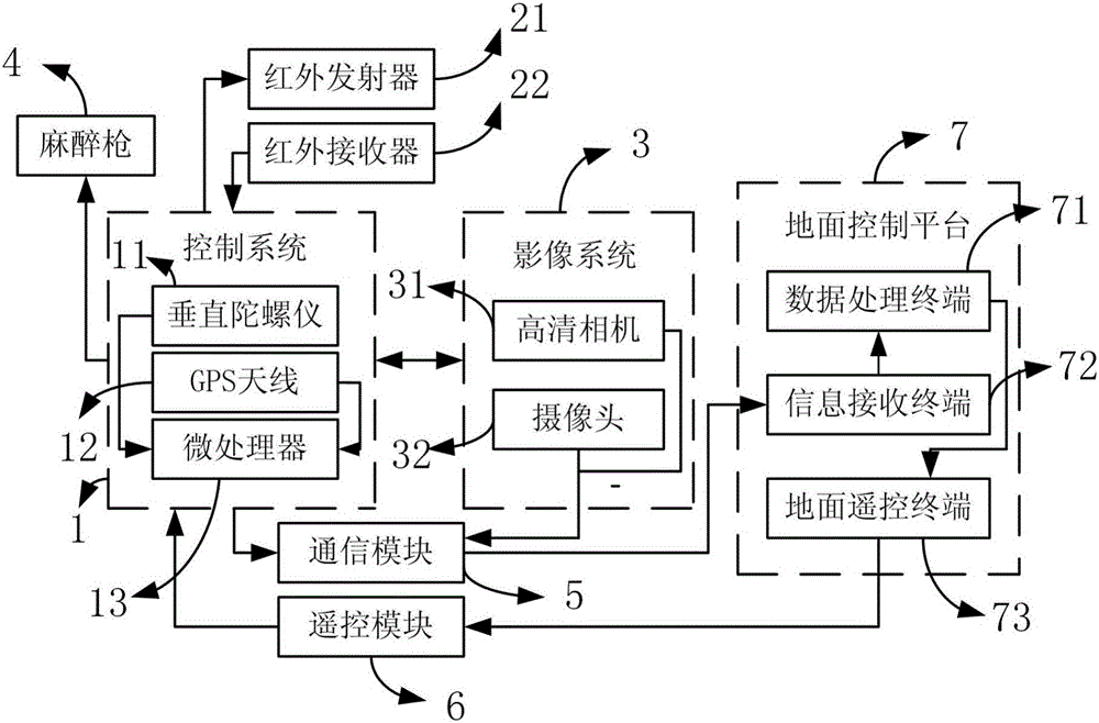
[0024] like figure 1 As shown, the drone with anesthesia function provided in Embodiment 1 includes a control system 1, an infrared system, an imaging system 3 and an anesthesia gun 4, and the control system 1 is electrically connected to the infrared system, the imaging system 3 and the anesthesia gun 4 . Further, the control system 1 includes a vertical gyroscope 11, a GPS antenna 12 and a microprocessor 13, the microprocessor 13 is used to control the drone, the vertical gyroscope 11 is electrically connected to the microprocessor 13, and the vertical gyroscope 11 is used for In order to control the balance of the UAV, it is controlled by the microprocessor 13 to correct the offset data of the UAV in real time and maintain the stable flight of the UAV. The GPS antenna 12 is used to obtain the geographic location information of the drone in real time. The GPS antenna 12 is electrically connected to the microprocessor 13, and is controlled by the microprocessor 13, and the p...

Embodiment 2

[0030]The remote tracking system provided in the second embodiment includes a ground control platform 7 and at least one of the above-mentioned drones with anesthesia function. The drone communicates with the ground control platform 7 remotely and is controlled by the ground control platform 7 . The ground control platform 7 includes a data processing terminal 71, an information receiving terminal 72 and a ground remote control terminal 73. The data processing terminal 71 is electrically connected with the information receiving terminal 72 and the ground remote control terminal 73, and the data processing terminal 71 is used for processing infrared characteristic signals and images. Characteristic signal, flight control signal and anesthesia action signal, the signal receiving terminal is used to receive the infrared characteristic signal, image characteristic signal, flight control signal and anesthesia action signal sent by the drone, and transmit the above-mentioned signals t...


PUM


Abstract

The invention discloses an unmanned plane having the anaesthesia function and belongs to the field of an unmanned plane. The unmanned plane comprises a control system, an infrared system and an image system, wherein the control system is electrically connected with the infrared system and the image system, an anaesthesia gun electrically connected with the control system is further comprised, the infrared system is used for acquiring infrared characteristics of a traced object, the image system is used for acquiring image characteristics of the traced object, and the control system is used for controlling the anaesthesia gun to realize the anaesthesia effect on the traced object according to the infrared characteristics and the image characteristics. The invention further discloses a remote tracing system comprising a ground control platform and at least one unmanned plane having the anaesthesia function. The unmanned plane having the anaesthesia function is advantaged in that the function of analyzing physiological characteristics of the traced object is realized, the remote anaesthesia effect on the traced object can be realized, and high intelligence level and easy control are realized.

Description

technical field [0001] The present invention relates to the field of unmanned aerial vehicles, and more specifically, relates to an unmanned aerial vehicle with anesthesia function and a remote tracking system with the above-mentioned unmanned aerial vehicle. Background technique [0002] In large safari parks or livestock farms, in order to treat or check ferocious or hard-to-catch tracked animals, it is often necessary to anesthetize them with anesthesia, and then perform treatment or check-ups. Sometimes scientists also need to treat tracked animals. Enter the positioning device for tracking and investigation, and complete the scientific experiment. Traditionally, an anesthesia gun is often used to shoot the tracked object. In this way, the tracker often needs to get close to the tracked object. This method not only puts the tracker in danger, but it is also very difficult to find the tracked object in a large wild animal park or livestock farm. difficult. [0003] Chin...

Claims


Application Information

Patent Timeline
Patent Type & Authority Applications(China)
IPC IPC(8): G05D1/12G05D1/10G08C17/02B64C39/02A01M27/00
CPCG05D1/12A01M27/00B64C39/02G05D1/101G08C17/02
Inventor 不公告发明人
Owner 佛山杰致信息科技有限公司
Learn More