Eureka AIR delivers breakthrough ideas for toughest innovation challenges, trusted by R&D personnel around the world.

Real-time visual experiment device of influence of temperature difference on heat transfer speed and demonstration method

An experimental device and heat transfer technology, applied in educational appliances, instruments, teaching models, etc., can solve problems such as misunderstanding of the physical nature of students, failure to see, etc., and achieve the effect of obvious phenomenon, simple structure, and low cost

Inactive Publication Date: 2016-10-26
SHAANXI NORMAL UNIV
View PDF9 Cites 0 Cited by
  • Summary
  • Abstract
  • Description
  • Claims
  • Application Information

AI Technical Summary

Problems solved by technology

Due to the invisibility of the heat conduction process of objects, the understanding of the relationship between temperature difference, thermal resistance and heat conduction speed is usually compared with resistance, voltage, current and the relationship between them in the teaching process of heat transfer, but because the conduction speed of materials does not It is not restricted by voltage and resistance, so this simple analogy often causes students to misunderstand the physical nature of the two
The relationship between temperature difference and heat conduction velocity is one of the basic issues in heat transfer. Realizing the real-time visual demonstration of the relationship between temperature difference and heat conduction velocity is of great significance in the teaching of heat transfer, but no such experimental demonstration has been seen so far. instrument

Method used


Image

  • Real-time visual experiment device of influence of temperature difference on heat transfer speed and demonstration method
  • Real-time visual experiment device of influence of temperature difference on heat transfer speed and demonstration method
  • Real-time visual experiment device of influence of temperature difference on heat transfer speed and demonstration method

Examples


Embodiment 1

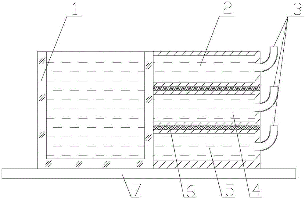
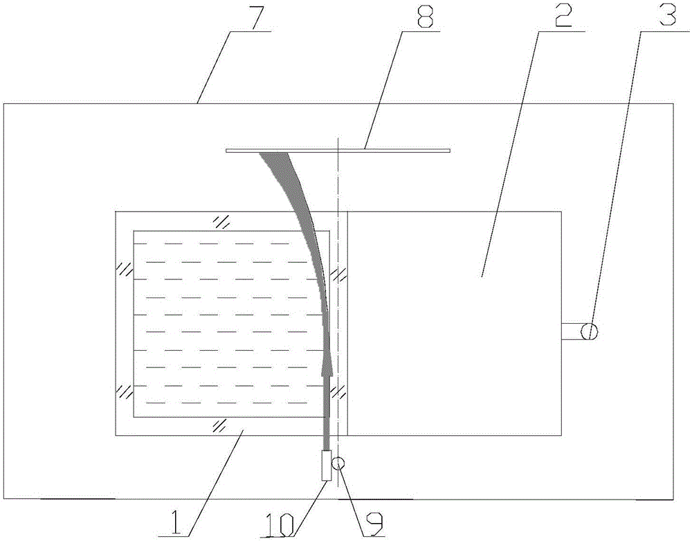
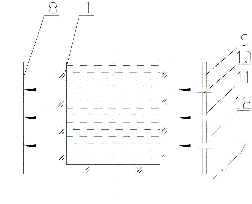
[0022] exist figure 1 , 2 , 3, the real-time visualization experimental device of the influence of temperature difference on heat transfer speed in this embodiment consists of water tank 1, upper water tank 2, water injection pipe 3, middle water tank 4, lower water tank 5, insulation layer 6, base 7, light screen 8, The laser bracket 9, the upper semiconductor laser 10, the middle semiconductor laser 11, and the lower semiconductor laser 12 are connected to form.

[0023] A water tank 1 is placed on the base 7. The water tank 1 of the present embodiment is a transparent glass water tank. On the outer surface of the right side wall of the water tank 1, an upper water tank 2, a middle water tank 4, and a lower water tank are connected from top to bottom with glue. 5. The upper water tank 2, the middle water tank 4, and the lower water tank 5 have the same volume. An insulation layer 6 is installed between the upper water tank 2 and the middle water tank 4. An insulation layer ...


PUM


Abstract

The invention provides a real-time visual experiment device of the influence of a temperature difference on a heat transfer speed. A base is provided with a transparent water tank. The outer surface of the right side wall of the water tank is provided with an upper water tank, a middle water tank and a lower water tank from top to bottom. Thermal insulation layers are arranged between the upper water tank and the middle water tank and between the middle water tank and the lower water tank. The right side walls of the upper water tank, the middle water tank, and the lower water tank are provided with water injection pipes which are communicated with the insides of the three water tanks. The back side wall outer base of the water tank is provided with a light screen. The front side wall outer base is provided with a laser bracket which is provided with an upper semiconductor laser, a middle semiconductor laser and a lower semiconductor laser from top to bottom. The real-time visual experiment device has the advantages of a simple structure, low cost, convenient carrying, and an obvious phenomenon and is very suitable for the classroom demonstration of heat transfer theory teaching.

Description

technical field [0001] The invention belongs to the technical field of heat transfer experiment equipment, and in particular relates to experimental equipment for heat transfer speed. Background technique [0002] As we all know, the heat transfer rate of the medium is determined by two factors, one is the temperature difference and the other is the thermal resistance. In the case of the same material and the same heat conduction thickness, that is, the same thermal resistance, the greater the temperature difference, the faster the heat conduction speed; correspondingly, under the same temperature difference, the greater the heat resistance, the slower the heat conduction speed. This is exactly where the principle of enhancing the thermal insulation effect is by increasing the thickness of the thermal insulation layer 6 . Due to the invisibility of the heat conduction process of objects, the understanding of the relationship between temperature difference, thermal resistanc...

Claims


Application Information

Patent Timeline
Patent Type & Authority Applications(China)
IPC IPC(8): G09B23/16
CPCG09B23/16
Inventor 张宗权时俊仙耿玉田玉龙徐铭
Owner SHAANXI NORMAL UNIV
Why Eureka
Eureka Blog
Learn More