Fireproof anti-vibration cable

A technology of cables and fire-resistant belts, which is applied in the direction of insulating cables, cables, circuits, etc., can solve the problems of local insulator damage, easy accidents, fire-proof and refractory layer damage, etc., and achieve the effect of reducing crosstalk

Inactive Publication Date: 2016-10-26
CHENGDU ZHIRENSHANYONG INFORMATION TECH CO LTD
View PDF0 Cites 0 Cited by
  • Summary
  • Abstract
  • Description
  • Claims
  • Application Information

AI Technical Summary

Problems solved by technology

[0002] Existing cables are generally made of all-copper or all-aluminum. Since copper cables are superior to aluminum in oxidation resistance, welding performance and electrical conductivity, they are widely used in transmission cables with large currents. Expensive and high density, it is replaced by aluminum conductors under certain conditions of use. With the continuous development of technology, the complexity and diversification of cable use occasions, copper or aluminum conductors are also somewhat inadequate in comprehensive use
[0003] At the same time, in the process of transportation or other use environments, the local insulator damage and fall off caused by the cable are not checked out immediately, which is easy to cause accidents during use, and at the same time, it takes manpower and increases labor costs during the detection process
In addition, some cables have relatively poor fire resistance
In a fire, the fire-resisting part of the cable is sometimes relatively small, and not the whole cable is roasted by the fire. This single-layer fireproof and refractory layer is easily damaged due to local hardening, thus losing its protective effect on the cable.

Method used


Image

  • Fireproof anti-vibration cable

Examples


Embodiment Construction

[0013] All features disclosed in this specification, or steps in all methods or processes disclosed, may be combined in any manner, except for mutually exclusive features and / or steps.

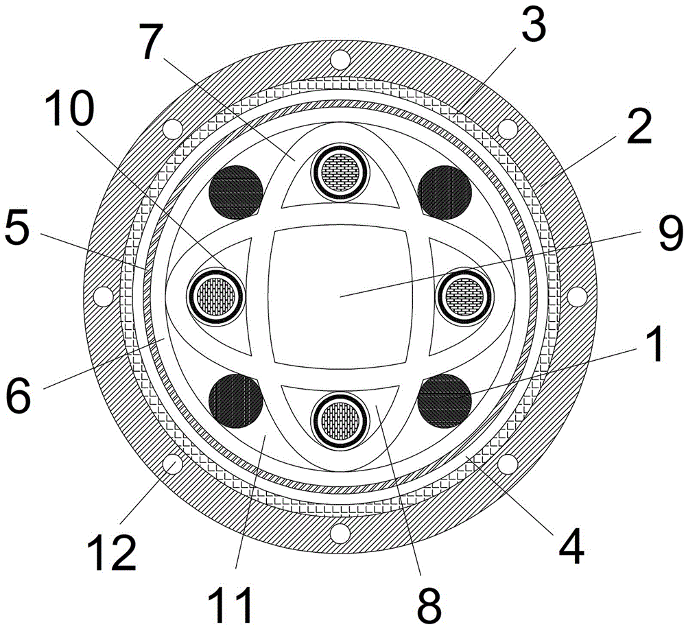
[0014] The present invention will be further described below in conjunction with accompanying drawing:

[0015] Such as figure 1 As shown, a fireproof and earthquake-resistant cable includes an outer insulating layer 2 and a filler layer 1 located in the insulating layer 2. The insulating layer 2 includes a first phlogopite tape, a composite fire-resistant tape and a second phlogopite mica tape from outside to inside. The composite refractory belt is calendered from a mixture of glass fiber cloth and ceramizable silicone rubber. The setting of glass fiber cloth helps to improve the strength when the ceramizable silicone rubber exhibits ceramic characteristics, and it is also convenient for the composite refractory belt. Molding; the outside of the insulating layer 2 is provided with an anti-b...


PUM


Abstract

The invention discloses a fireproof anti-vibration cable comprising an external insulating layer and a filler layer which is arranged in the insulating layer. The internal side of the insulating layer is provided with a fireproof isolation layer, a thin aluminum powder layer, a metal protective layer and a silicon rubber internal sheath in turn. The silicon rubber internal sheath has an inner aperture of which the cross section is circular. The aperture is internally provided with a "cross"-shaped silicon rubber compression resistant strip. The four corners of the silicon rubber compression resistant strip are provided with conductor cavities. Each conductor cavity is internally provided with a cable core. The cable core comprises a conductor layer, a metal braided layer and an insulator layer which are arranged from inside to outside. The middle position of the silicon rubber compression resistant strip is provided with a compression resistant cavity. The gaps of the four corners of the silicon rubber compression resistant strip are provided with extruding strips. The extruding strips are simultaneously contacted with the silicon rubber internal sheath and the silicon rubber compression resistant strip. The internal side of the insulating layer is also provided with the metal protective layer and the fireproof isolation layer so that effective fire resistance can be realized; and buffering of the silicon rubber compression resistant strip is facilitated by the silicon rubber compression resistant strip so that a balance is formed, and the cable has great anti-vibration and compression resistant performance.

Description

technical field [0001] The invention relates to the technical field of power transmission, in particular to a cable. Background technique [0002] Existing cables are generally made of all-copper or all-aluminum. Since copper cables are superior to aluminum in oxidation resistance, welding performance and electrical conductivity, they are widely used in transmission cables with large currents. Expensive and high density, it is replaced by aluminum conductors under certain conditions of use. With the continuous development of technology, the complexity and diversification of cable use occasions, copper or aluminum conductors are also somewhat powerless in comprehensive use. [0003] At the same time, in the process of transportation or other use environments, the local insulator caused by the cable is damaged or falls off without immediate inspection, which is likely to cause accidents during use. At the same time, the inspection process requires manpower and increases labor ...

Claims


Application Information

Patent Timeline
Patent Type & Authority Applications(China)
IPC IPC(8): H01B7/295H01B7/18H01B7/22
CPCH01B7/295H01B7/189H01B7/1895H01B7/221
Inventor 张凯胜刘华吴小莉
Owner CHENGDU ZHIRENSHANYONG INFORMATION TECH CO LTD
Why Eureka
Try Eureka