
Time synchronization method and system for wire1ess sensor network

A wireless sensor network and time synchronization technology, applied in the field of visible light communication and wireless sensor network, can solve the problems of low synchronization accuracy and long synchronization time, and achieve the effect of reducing energy consumption, time and hierarchy.

Inactive Publication Date: 2016-10-26
NORTHWESTERN POLYTECHNICAL UNIV
View PDF5 Cites 4 Cited by
  • Summary
  • Abstract
  • Description
  • Claims
  • Application Information

AI Technical Summary

Problems solved by technology

[0008] In order to solve the above problems, the present invention provides a method for overcoming the defects of low synchronization accuracy and long time required for synchronization in the prior art, and provides a method for time synchronization using visible light

Method used


Image

  • Time synchronization method and system for wire1ess sensor network
  • Time synchronization method and system for wire1ess sensor network
  • Time synchronization method and system for wire1ess sensor network

Examples


Embodiment Construction

[0025] The following describes in detail a time synchronization method and system in a wireless sensor network of the present invention with reference to the drawings.

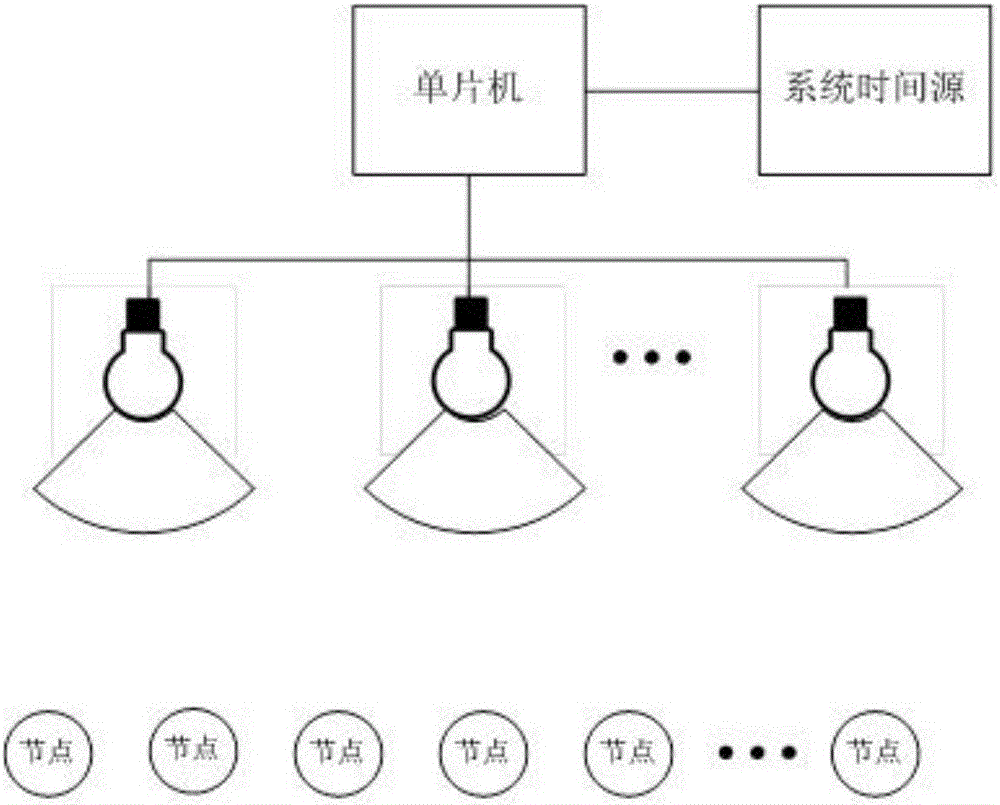
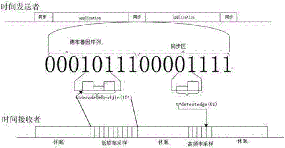
[0026] A method of time synchronization in wireless sensor network such as figure 1 Shown: the time sender informs the time receiver the location of the time synchronization point through visible light communication, and the time receiver uses the received time synchronization point for time synchronization; the time synchronization point is a specific time in the transmitted signal For the upper or lower edge within a segment, the specific time period is a synchronization area, and there is only one upper or lower edge in the synchronization area to indicate the time synchronization point.

[0027] The system structure is like figure 2 As shown, it includes a time transmitting end and a time receiving end. The time transmitting end includes a single-chip microcomputer and a visible light source. The single-chip mi...


PUM


Abstract

The invention discloses a time synchronization method and system for a wire1ess sensor network. A time sender informs a time receiver of time information about the position of a time synchronization point via visible light communication, and the time receiver performs time synchronization using the received time synchronization point; the time synchronization point is a hop-up edge or a hop-down edge within a specific time period in sent signals, the specific time period is a synchronization zone, and the synchronization zone has only one hop-up edge or hop-down edge for indicating the time synchronization point. According to the time synchronization method based on visible light communication, all sensor nodes can directly perform time synchronization on a visible light source, so that the levels of the tree structure of the original synchronization method are reduced and the synchronization precision is improved. Each time synchronization is not limited by the maximum amplitude in the absence of a tree clock topology, so that the time required by the time synchronization process is effectively reduced.

Description

Technical field [0001] The invention belongs to the technical field of visible light communication and wireless sensor network, and relates to a method for time synchronization in a wireless sensor network using visible light. Background technique [0002] Visible light communication (VLC) is a wireless optical communication technology that uses high-speed light and dark flashing light signals that are invisible to the naked eye to transmit information. This technology provides access to several hundred THz of licensed spectrum, immunity to electromagnetic interference, and non-interference with radio frequency (RF) systems. VLC technology also provides additional security by allowing only specific users to receive transmission signals, and provides enhanced and supplementary communications from existing services (eg, lighting, display, indication, decoration, etc.) from visible light infrastructure. [0003] In recent years, wireless sensor network technology has gradually steppe...

Claims


Application Information

Patent Timeline
Patent Type & Authority Applications(China)
IPC IPC(8): H04J3/06H04W52/02
CPCH04B10/116H04J3/0605H04J3/0635H04W52/0274H04W84/18Y02D30/70
Inventor 杨哲赵华阎岩曹辉程琛黄鑫李士宁
Owner NORTHWESTERN POLYTECHNICAL UNIV
Learn More