Construction method of high-rise steel structure frame beam

A steel structure frame and construction method technology, applied to truss structures, joist beams, girders, etc., can solve hidden safety hazards in high-altitude construction, without considering cranes, safety risks, etc., to improve construction quality and construction efficiency, solve Construction safety issues and the effect of reducing construction costs

Active Publication Date: 2018-05-01
CHINA 22MCC GROUP CORP
View PDF3 Cites 0 Cited by
  • Summary
  • Abstract
  • Description
  • Claims
  • Application Information

AI Technical Summary

Problems solved by technology

What's more, the erection of the operation platform also needs to be dismantled under the premise of protecting the base material, and the position of the removed solder joint needs to be polished and derusted → the painting process is very troublesome, and the final material used can hardly be reused (the size is too short), It can only be disposed of by waste, which is costly and uneconomical. This kind of solution is generally not recommended;
[0010] The second method is that the bearing capacity of the floor needs to meet the requirements of the dynamic load of the crane. For some special engineering environments, the floor design does not take into account the factors caused by the dynamic load bearing capacity of the crane. In this case, the crane is useless, not to mention the cost is too high. It is recommended to select according to the actual situation on site;
[0011] The third method is that the bearing capacity of the floor needs to meet the requirements of the dynamic load of the climbing vehicle. For some special engineering environments, the floor design does not take into account the dynamic load bearing capacity of the climbing vehicle, so the climbing vehicle is useless, even if the load can meet the construction requirements. , and the maximum lifting height and position of the climbing car in some special areas are also unreachable, not to mention that the cost is too high, it is recommended to choose according to the actual situation on site;
[0012] The fourth method is to build steel structure pipe scaffolding to complete the construction task. The scaffolding itself is subject to height and safety construction restrictions, and there are certain safety risks in construction.
That is to say, there are two schemes: scheme 1. Scaffolding is limited by height from the ground to the construction position, the project volume is too large, and each node needs to be erected, which will be a huge project; scheme 2 is erected by cantilever method at the installation position There are potential safety hazards and dangers of high-altitude construction on the small-scale operation platform; the scaffolding of the above two schemes needs to be erected and dismantled, and it is the only one erected at a fixed point, with a huge amount of work, high cost and uneconomical. Situation selection;
[0013] The fifth method is to set up movable scaffolding to complete the construction task. Although this scheme can solve some construction problems of low-rise nodes, there are three problems in erecting movable scaffolding that cannot be ignored: First, there are certain restrictions on the construction height of erecting movable scaffolding For the height exceeding the standard limit, the construction cannot be satisfied; secondly, there are certain safety hazards and risks in the construction of the movable scaffolding itself, and it is also subject to safety construction restrictions; thirdly, the working environment of the movable scaffolding is that the ground is flat and has a certain load requirements, but usually the steel structure frame is constructed before the floor platform, so that the movable scaffold cannot be put in place layer by layer, and the construction is subject to certain restrictions. This scheme needs to be selected according to the actual situation on site

Method used


Image

  • Construction method of high-rise steel structure frame beam
  • Construction method of high-rise steel structure frame beam
  • Construction method of high-rise steel structure frame beam

Examples


Embodiment Construction

[0044] The present invention will be described in detail below with reference to the drawings and embodiments:

[0045] The construction sequence of the steel structure frame is: 1. Frame column installation; 2. Frame steel beam installation 3. Frame steel structure installation node processing is perfect 4. Frame steel structure platform concrete (or floor deck + concrete) pouring construction, continue to the next Stage frame column installation.......

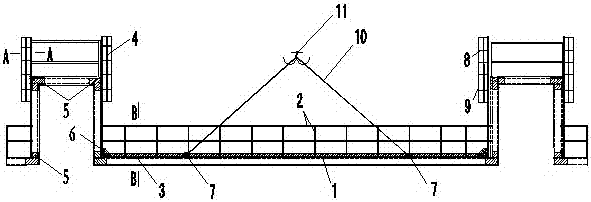
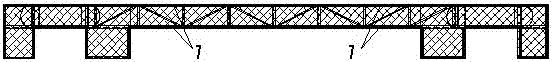
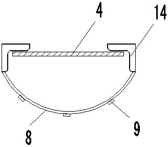
[0046] Attached Figure 1-4 It can be seen that a construction method of a high-rise steel frame beam includes the following steps:

[0047] Step 1, steel structure construction sequence, frame steel beams are installed in place;

[0048] Step 2. Use hoisting machinery to move the bridge to a connecting end point of a set of steel beams opposite to the installation position;

[0049] Step 3, hoisting in place across the bridge:

[0050] Step 4, the construction personnel will use the bridge to carry out the construction work at the c...


PUM


Abstract

The invention relates to a construction method of high-rise steel structure frame beams, which includes the following steps: a) mounting the steel structure frame beams on designed positions according to construction sequence of a steel structure; b) by means of a hoisting machine, moving a bridge to a connection end point of a group of opposite steel beams which has been mounted on the designed positions; c) hoisting the bridge to the designed positions; d) performing construction operation of the connection points on the bridge by constructors; d) when construction of one connection end point of the steel beam is finished, moving the bridge by means of the hoisting machine to a connection end point at the other opposite end of the steel beams which have been mounted on the designed positions, and performing construction. In the construction method, a certain number of bridges are produced according to actual work load and demand on construction period of the project, so that construction demand is satisfied in a manner that the hoisting machine repeatedly hoists and moves the bridges, wherein the bridges can be used repeatedly and are convenient to transport and operate. The construction method guarantees security of workers, reduces risk of safety accident, reduces construction cost and improves construction quality and efficiency.

Description

Technical field [0001] The invention relates to a building construction method, in particular to a construction method of a high-rise steel frame beam. Background technique [0002] In the conventional installation of steel frame beams and columns in high-rise (or shaped municipal projects), the methods usually used are: [0003] 1. Use the external climbing ladder to reach the platform steel beam installation position from the ground, and then use the steel structure material welding method to build the construction operation platform at the installation node position according to the site conditions, so as to carry out the bolting, welding or bolt welding of the installation port position; [0004] 2. Use the operating crane to hoist the cage to carry out bolt welding at the position of the installation port; [0005] 3. Use the method of positioning the lifting cage to carry out the bolt welding operation at the position of the installation port; [0006] 4. Use the method of erecti...

Claims


Application Information

Patent Timeline
Patent Type & Authority Patents(China)
IPC IPC(8): E04C3/04E04G21/14
CPCE04C3/04E04G21/14
Inventor 李成杰
Owner CHINA 22MCC GROUP CORP
Why Eureka
Try Eureka