Intelligent street lamp illuminating device

A technology for lighting devices and smart street lamps, applied in the field of control systems, can solve problems such as poor real-time interaction, weak adaptive adjustment capability, and lack of emergency handling, and achieve the effects of convenient installation and cost reduction.

Active Publication Date: 2016-11-02
重庆联国信息工程有限公司
5 Cites 12 Cited by

AI-Extracted Technical Summary

Problems solved by technology

However, the existing light bulb group control system still has the disadvantages of poor...

Method used

Except lighting work, also be provided with the functional structure that can provide other public services in the present embodiment, wherein, video camera 27 can realize networking monitoring, is used for intelligent identification or public security; Environmental monitor 28 can be used for intelligent sensing to carry out Collection of environmental data; the broadcaster 29 can realize intelligent broadcasting, which is used for government advertisement or emergency command; the first display 30 can be used for information interaction, for government announcements, information release or information query; the emergency helper 32 can realize one-key help 1. The function of voice intercom; the setting of the charging interface 31 can realize the emergency charging of the mobile terminal equipment, which brings convenience to people's life. In this way, integrating various functional structures into the street lamp assembly 3 can not only optimize the occupied space, but also facilitate management and maintenance.
In the present embodiment, the cooperation between carrier concentrator 4 and carrier terminal 5 can realize the communication between single lamp controller 2 and centralized controller 1, like this, single lamp controller 2 can accept centralized controller 1 The command. By using power carrier communication, there is no need to lay communication lines, which not only reduces the cost, but also brings convenience t...

Abstract

The invention discloses an intelligent street lamp illuminating device. The intelligent street lamp illuminating device comprises an integrated controller, a carrier concentrator, carrier terminals and a plurality of street lamp assemblies. Each street lamp assembly is provided with a single lamp controller which is used for controlling operation of the street lamp assembly and connected with the corresponding carrier terminal. Each street lamp assembly comprises a lamp post, a lamp holder and a bulb set; a camera, an environment detector, a public addressor, a first displayer, an emergent help seeker and a wireless communication module are arranged on the lamp post; and the intelligent street lamp illuminating device further comprises an antitheft assembly. Multiple functional structures are integrated into the street lamp assemblies, illuminating working can be achieved, and multifunctional road services such as electronic eyes, environment monitoring, intelligent broadcasting and information interaction can also be achieved. Accordingly, the occupied space is optimized, and management and maintenance can be facilitated.

Application Domain

Mechanical apparatusLighting support devices +7

Technology Topic

Integrated controllerEngineering +4

Image

  • Intelligent street lamp illuminating device
  • Intelligent street lamp illuminating device
  • Intelligent street lamp illuminating device

Examples

  • Experimental program(1)

Example Embodiment

[0039] Example 1
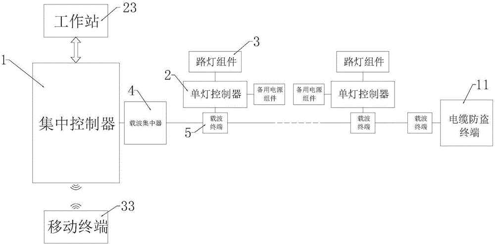
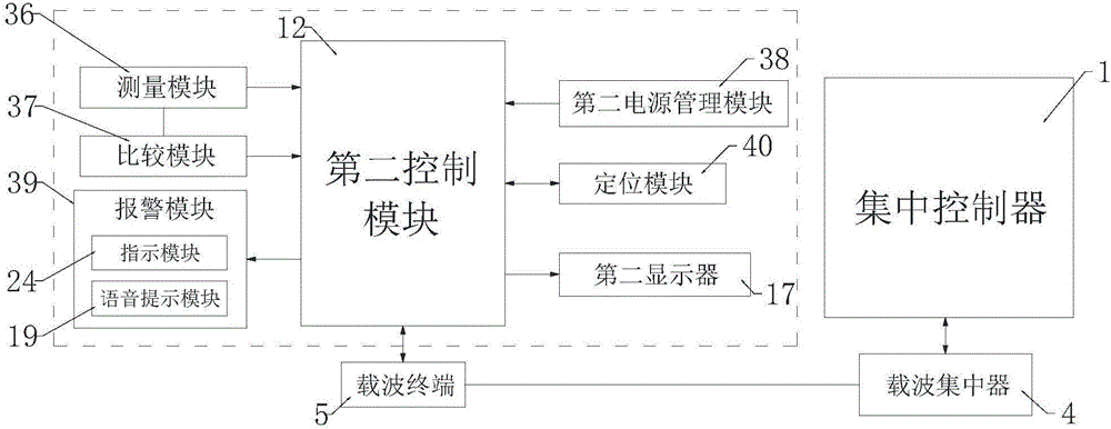
[0040] Such as Figure 1 to Figure 5 As shown, an intelligent street lamp lighting device includes a centralized controller 1, a carrier concentrator 4 connected to the centralized controller 1, a carrier terminal 5 matched with the carrier concentrator 4, and several street lamp components. All are equipped with a single lamp controller 2 used to control the operation of street lamp components and connected to the carrier terminal 5;
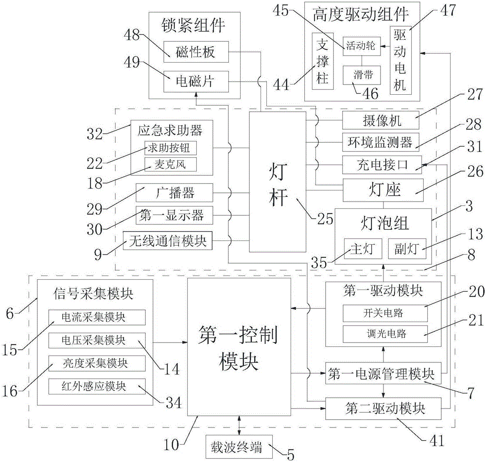
[0041] The single lamp controller 2 includes a first control module 10 that communicates with the carrier terminal, a signal acquisition module 6, a first power management module 7 and a first drive module 8 connected to the bulb group 3, a signal acquisition module 6, a first power supply Both the management module 7 and the first drive module 8 are connected to the first control module 10, and the first power management module 7 is connected to the first drive module 8;
[0042] The street lamp assembly includes a lamp post 25, a lamp holder 26 installed on the lamp post 25, and a bulb group 3 installed on the lamp holder 26. The lamp post 25 is provided with a camera 27, an environmental monitor 28, a broadcaster 29, and a first display. 30. The emergency helper 32 and the wireless communication module 9, the emergency helper 32 and the first display 30 are all connected to the first control module 10. The light pole 25 is also provided with a charging interface electrically connected to the first power management module 7 31;
[0043] It also includes an anti-theft component. The anti-theft component includes a number of cable anti-theft terminals 11 connected to the carrier terminal 5. The cable anti-theft terminal 11 includes a second control module 12, a measurement module 36, a comparison module 37, a second power management module 38, and an alarm module 39 And the positioning module 40, the measurement module 36, the comparison module 37, the second power management module 38, and the positioning module 40 are all connected to the second control module 12, and the measurement module 36 is connected to the comparison module 37.
[0044] In this embodiment, the cooperation between the carrier concentrator 4 and the carrier terminal 5 can realize the communication between the single-lamp controller 2 and the centralized controller 1, so that the single-lamp controller 2 can accept commands from the centralized controller 1. With the use of power carrier communication, there is no need to lay communication lines, which not only reduces the cost, but also brings convenience to the installation of the single lamp controller 2.
[0045] The single-lamp controller 2 is used to control the corresponding bulb group 3, wherein the signal acquisition module is used to collect the data information of the operation of the bulb group 3; the first power management module 7 is used to convert the mains power into the first The driving module 8 and the wireless communication module 9 supply low voltage; the first driving module 8 is used to drive the switch and voltage regulation of the light bulb group 3. The first control module 10 serves as the main controller, and can be programmed in an embedded device or programmable logic device with existing software to control the operation of each module.
[0046] In application, each single-lamp controller 2 has a unique address code. In this way, the centralized controller 1 can issue commands through the feedback of a single-lamp controller 2 to control the corresponding single-lamp controller 2 Switch, turn off the lights, and adjust the voltage of the bulb group 3. When the bulb group on a certain road section fails and stops running, the information collected by the signal collection module 6 transmits the collected data to the first control module 10, and the first control module 10 obtains the fault information after logical judgment And the fault type, and then feed the data back to the centralized controller 1 through the power carrier communication. In this way, the manager can know the specific address of the faulty section in time to facilitate timely maintenance.
[0047] The cable anti-theft terminal 11 is used to monitor the power status of each phase line of the low-voltage line. In application, install the cable anti-theft terminal 11 on the load end of the power cable and some nodes of the backbone line, and connect it directly to the low-voltage line The three-phase four-wire loop. Among them, the measurement module 36 is used to measure the power data of the power cable, and the comparison module 37 is used to compare with the measurement value of the measurement module 36, and then the second control module 12 can determine the power state of each phase line, and the positioning module 40 uses The status of geographical location. When a certain section of power cable is stolen, the cable anti-theft terminal 11 transmits the monitored road section information to the centralized controller 1 through power carrier communication.
[0048] In addition to lighting work, this embodiment is also provided with a functional structure that can provide other public services. Among them, the camera 27 can realize networked monitoring for intelligent identification or public security; the environmental monitor 28 can be used for intelligent sensing for environmental data Collection; the broadcaster 29 can realize intelligent broadcasting for government advertising or emergency command; the first display 30 can be used for information interaction, for government announcements, information release or information inquiry; the emergency helper 32 can realize one-key help, voice pairing Talking about the function; the setting of the charging interface 31 can realize emergency charging of mobile terminal equipment, bringing convenience to people's lives. In this way, the integration of various functional structures into the street lamp assembly 3 can not only optimize the occupied space, but also facilitate management and maintenance.
[0049] Preferably, the signal acquisition module 6 includes a current acquisition module 15, a voltage acquisition module 14, a brightness acquisition module 16 and an infrared sensor module 34. In this embodiment, the current collection module 15 is used to collect current information of the bulb group 3, the voltage collection module 14 is used to collect voltage information of the bulb group 3, the brightness collection module 16 is used to collect the brightness of the outdoor environment, and the infrared sensor module 34 Used to collect people or vehicle information. The information collected by the current collection module 15 and the voltage collection module 14 can be used to determine the working status of the bulb group 3, and the information collected by the brightness collection module 16 can be used to determine whether the brightness of the bulb group 3 meets the requirements. The infrared sensor module 27 It can be judged whether the street lamp assembly needs to be started according to the collected information. The feedback of these information data can facilitate the centralized controller 1 to control the individual lamp controllers 2, and at the same time, can reduce the power consumption of the entire system. In application, the infrared sensor module 27 can be arranged every two street lamp assemblies 3, so that it can save energy without hindering the night lighting work.
[0050] In order to realize the driving control of the bulb group 3 by the first driving module 8, preferably, the first driving module 8 includes a switch circuit 20 and a dimming circuit 21; the bulb group 3 includes a main lamp 35 and a sub lamp 13. The switch circuit 20 is used to control the turning on and light of the bulb group 2; the dimming circuit 21 is used to adjust the power of the bulb group 3. Normally, the first driving module 10 is used to drive the main lamp to perform lighting work, and the auxiliary lamp 13 is driven to perform lighting only when the main lamp 35 fails. In this way, the street lamp assembly can be prevented from being out of service during maintenance.
[0051] Preferably, the wireless communication module 9 is a WIFI module. The WIFI module is used to realize a wireless city, so that all residents can access the Internet wirelessly.
[0052] In order to visually observe the data information of the cable anti-theft terminal 11 and realize the voice intercom function of the emergency helper 32, preferably, it further includes a second display 17 connected to the second control module 12; the alarm module 39 includes The voice prompt module 19 and the instruction module 19; the emergency helper 32 is provided with a help button 22 and a microphone 18.
[0053] Further, it also includes a workstation 23 and a mobile terminal 33 communicating with the centralized controller 1. The centralized controller 1 can communicate with the workstation 23 through the GPRS module or Ethernet; the centralized controller 1 can communicate with the mobile terminal 33 through the GPRS module or the GSM module, which facilitates the remote monitoring and centralized control of the workstation 23 and the mobile terminal 33 The controller 1 further realizes the monitoring of each single lamp controller 2.
[0054] Preferably, the single-lamp controller 2 is further provided with a second driving module 41, which is connected to both the first control module 10 and the first power management module 7; each of the street lamp components It is also equipped with a height drive assembly electrically connected to the second drive module 41.
[0055] When the bulb group 3 fails or the single-lamp controller 2 needs to be maintained, the centralized controller 1 can send a command to the target single-lamp controller 2 so that the first control module 10 controls the second drive module 41 to act on the height The driving component, and the height driving component drive the lamp holder 26 to move down to a suitable height. In this way, it is convenient for management personnel to repair or maintain the bulb assembly 3. After the repair or maintenance is completed, the second driving module 41 is controlled by the first control module 10 to act on the height driving assembly, so that the height driving assembly drives the lamp holder 26 to move upward until it is reset.
[0056] In order to realize the adjustment of the height position of the lamp holder 26 by the height drive assembly, preferably, a receiving cavity 42 is provided in the lamp post 25, and a movable opening 43 communicating with the receiving cavity 42 is provided on the side wall of the lamp post 25; The height drive assembly includes a support column 44 arranged in the accommodating cavity 42. The upper and lower ends of the support column 44 are provided with movable wheels 45, and also includes a sliding belt 46 and a driving motor 47. The sliding belt 46 is sleeved on the two movable wheels 45 And cooperate with the two movable wheels 45, the driving motor 47 is electrically connected to the second driving module 41, and the driving motor 47 can drive the movable wheels 45 to rotate; one end of the lamp holder 26 passes through the movable opening 43 and the sliding belt 46 It is fixedly connected, and the lamp holder 26 is matched with the movable opening 43.
[0057] In this embodiment, the lamp holder 26 cooperates with the movable opening 43, so that the lamp holder 26 can slide up and down in the movable opening 43, and can also support the lamp holder 26 to avoid shaking when it slides. The upper and lower ends of the support column 44 are provided with movable wheels 45, one of which is a driving wheel and the other is a driven wheel. In application, when the lamp holder 26 needs to be moved, the centralized controller 1 sends a command to the target single-lamp controller 2 so that the first control module 10 controls the second drive module 41 to act on the drive motor 47, and the drive motor 47 is driven as active When the movable wheel 45 of the wheel rotates, the sliding belt 46 is driven to slide, thereby driving the lamp holder 26 fixedly connected to it to move up and down.
[0058] Preferably, each of the street lamp components is also equipped with a locking component, the locking component includes an electromagnetic sheet 49 with a magnetic plate 48 that can be magnetically matched with the magnetic plate 48, and the magnetic plate 48 is arranged on the light pole 25 and close to the lamp post 25. At the movable opening 43, the electromagnetic sheet 49 is located on the lamp holder 26 and is connected to the second driving module 41.
[0059] In this embodiment, the first control module 10 acts on the second drive module 41, so that the second drive module 41 drives the electromagnetic sheet 49 to generate a magnetic field that can attract and cooperate with the magnetic plate 48, so that the lamp holder 26 can be Fixed in the movable opening 43. Through the arrangement of this locking assembly, the height position of the lamp holder 26 can be fixed to prevent it from shaking. In this way, the bearing burden of the sliding belt 46 can be reduced, and the convenience of fixing the lamp holder 26 can be improved. It has the advantages of convenient operation, good firmness and long service life.
[0060] In order to reduce the sliding friction between the lamp holder 26 and the movable opening 43, preferably, elastic gaskets are provided on both sides of the lamp holder 26.

PUM

no PUM

Description & Claims & Application Information

We can also present the details of the Description, Claims and Application information to help users get a comprehensive understanding of the technical details of the patent, such as background art, summary of invention, brief description of drawings, description of embodiments, and other original content. On the other hand, users can also determine the specific scope of protection of the technology through the list of claims; as well as understand the changes in the life cycle of the technology with the presentation of the patent timeline. Login to view more.

Similar technology patents

Apparatus and method for low-density cellular wood plastic composites

InactiveUS20050067729A1less-expensivelow cost
Owner:STRANDEX CORP

Haptic trackball device

InactiveUS7710399B2simple actuatorlow cost
Owner:IMMERSION CORPORATION

Steering Arrangement for a Trailer

InactiveUS20110018231A1low cost
Owner:ZF FRIEDRICHSHAFEN AG

Classification and recommendation of technical efficacy words

  • low cost
  • Easy to install

System and method for transmitting wireless digital service signals via power transmission lines

ActiveUS7929940B1reduce bandwidth requirementlow cost
Owner:NEXTEL COMMUNICATIONS

System and method for determination of position

InactiveUS20090149202A1low costreduce requirement
Owner:STEELE CHRISTIAN

Adaptive antenna optimization network

InactiveUS6961368B2low costminimal space
Owner:ERICSSON INC

Antenna device and method for attaching the same

ActiveUS20150138022A1low costimproved strength characteristic
Owner:NEC CORP

Cooking electric appliance

PendingCN107647763AEasy to installAvoid insulation loss
Owner:FOSHAN SHUNDE MIDEA ELECTRICAL HEATING APPLIANCES MFG CO LTD

System for monitoring vibration of rotating machinery rolling bearing in wireless mode

InactiveCN102053016Ameasurementanalysisdatareal-timeEasy to install
Owner:JIANGSU UNIV
Why Eureka
Try Eureka