

Circulating fluidized bed boiler air supply device
A technology of circulating fluidized bed and air supply device, which is applied to fluidized bed combustion equipment, fuel burning in a molten state, lighting and heating equipment, etc., can solve problems such as coking accidents, uneven flow field, etc. The effect of slag leakage, improving efficiency and improving performance
- Summary
- Abstract
- Description
- Claims
- Application Information
AI Technical Summary
Problems solved by technology
Method used
Image

Examples
Embodiment Construction
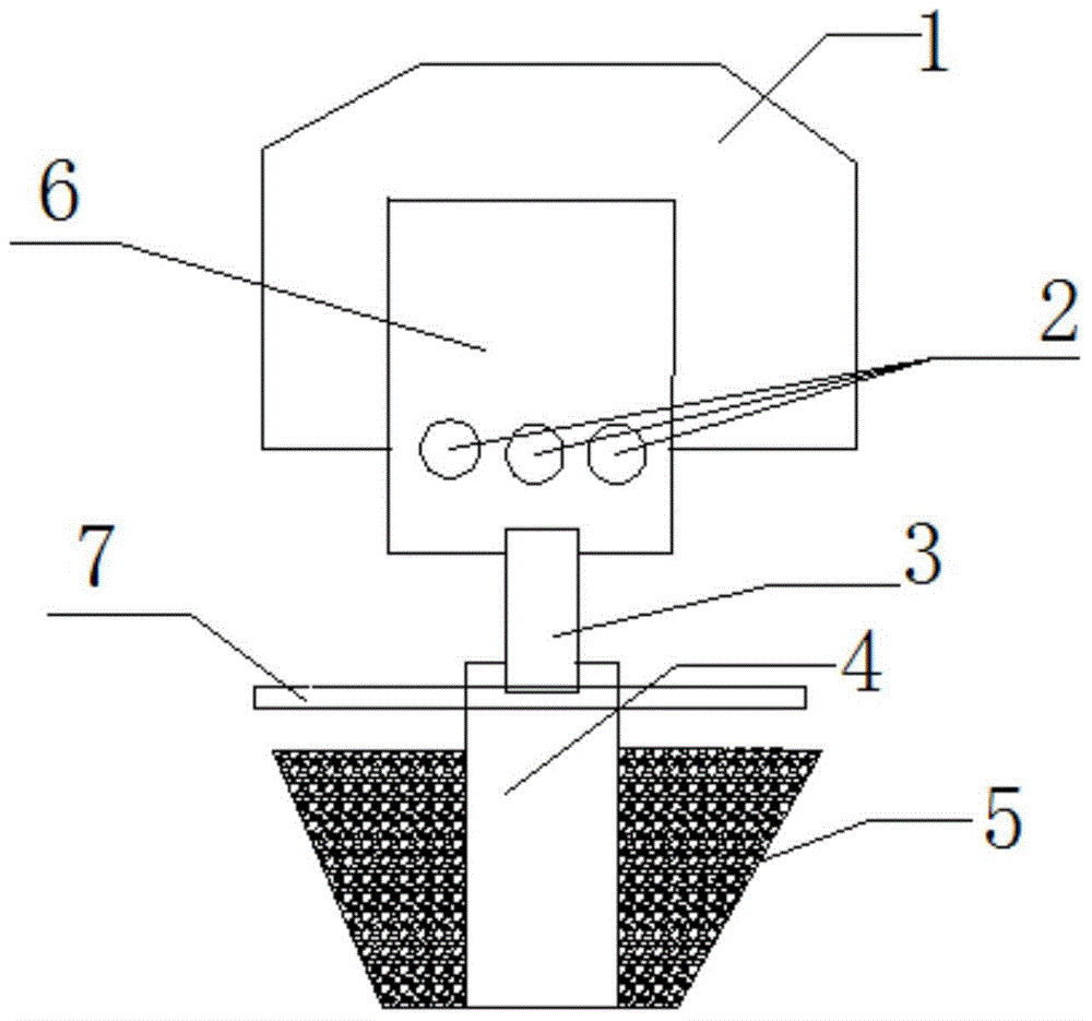
[0007] The present invention will be described in further detail below in conjunction with the accompanying drawings.
[0008] see figure 1 , the present invention includes an air distribution plate 7 with an air inlet and a wind cap 1 arranged on the upper air distribution plate 7, and an adjusting member 3 for adjusting the air intake is arranged at the air inlet of the upper air distribution plate 7. Wherein the adjusting part 3 is connected with the push rod 4 . The adjusting part 3 is a ring-shaped plate structure set in the air inlet of the air distribution plate 7. The opening diameter of the air cap 1 accounts for 1 / 3-2 / 3 of the entire area of the air distribution plate 7, and the opening of the air cap 1 in the central area The ratio of the aperture diameter of the hole to the aperture diameter of the opening 2 of the wind cap 1 in the remaining area is 3:5-4:5.
[0009] Its working process is as follows: before the boiler starts, the air inlet of the lower air di...
PUM
 Abstract
Description
Claims
Application Information