Check patentability & draft patents in minutes with Patsnap Eureka AI!

Current detection circuit and display system

A technology of current detection circuit and feedback current, which is applied in the direction of measuring current/voltage, measuring device, measuring electrical variables, etc., can solve the problems of increased reaction time, decreased driving speed, unevenness, etc., and achieves low power consumption, improved accuracy, The effect of short working hours

Active Publication Date: 2016-11-02
PEKING UNIV SHENZHEN GRADUATE SCHOOL
View PDF7 Cites 12 Cited by
  • Summary
  • Abstract
  • Description
  • Claims
  • Application Information

AI Technical Summary

Problems solved by technology

In the scheme of external detection and compensation, the pixel circuit of the current-driven pixel circuit can be detected in real time to compensate the threshold voltage drift or non-uniformity of the driving transistor, but when the driving circuit of the pixel circuit is small, its response time will increase. The driving speed will drop, so the current driven pixel circuit is less commonly used
Therefore, the current external detection and compensation schemes are all focused on solving the threshold voltage drift and non-uniformity of the driving transistor in the voltage-driven pixel circuit.

Method used


Image

  • Current detection circuit and display system
  • Current detection circuit and display system
  • Current detection circuit and display system

Examples


Embodiment 1

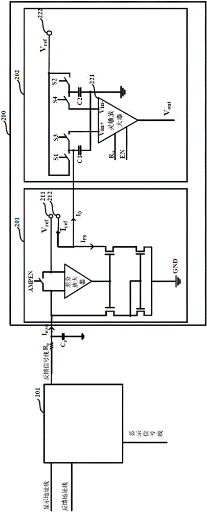
[0039] The current detection circuit 200 of this embodiment is used to detect the feedback current of the pixel unit, please refer to image 3 , which includes a feedback unit 201 and a current comparison unit 202 .

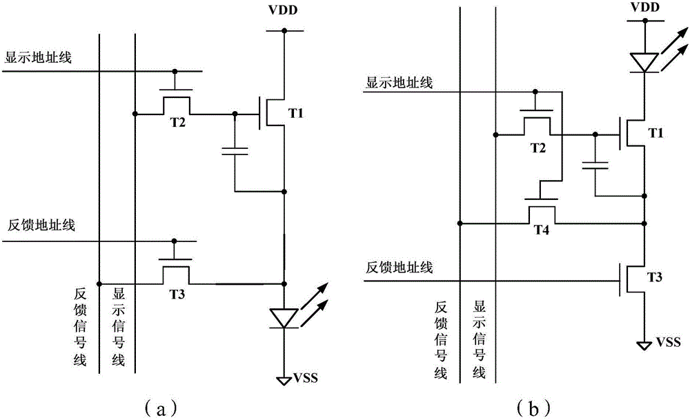
[0040] The feedback unit 201 is used for receiving and replicating the feedback current, and subtracting the feedback current from an expected current to output. As mentioned above, the driving transistor T1 is driven by the detection signal to generate a feedback current. According to the voltage of the detection signal, the magnitude of the feedback current generated by the driving transistor T1 can be calculated according to the formula, which is the expected current. If the actual feedback current is Inconsistency with the expected current indicates that the threshold of the pixel unit, specifically, the threshold of the driving transistor T1 has drifted; in addition, the threshold of the driving transistor T1 after the drift can be calculated according to th...

Embodiment 2

[0055] This embodiment provides a simplified current detection circuit, and the difference from the first embodiment lies in the current comparison unit 202, which will be described in detail below.

[0056] Please refer to Image 6 , the current comparison unit 202 of this embodiment includes a capacitor C1 for converting the current difference output by the feedback unit 201 into a voltage, and for comparing the capacitor C1 with a second reference voltage source V ref2 A sense amplifier that amplifies the voltage difference. In one embodiment, specifically, the first end of the capacitor C1 is grounded, the second end of the capacitor C1 is connected to the output end of the feedback unit 201, and the second end of the capacitor C1 is also connected to the second reference voltage source V through a switch S1. ref2 connected, the second terminal of capacitor C1 is also connected with one input terminal Vin+ of the sense amplifier, and the other input terminal Vin- of the s...


PUM


Abstract

The invention discloses a current detection circuit and a display system. The current detection circuit is used for detecting the feedback current of a pixel unit and comprises a feedback unit used for receiving and copying the feedback current, performing subtraction on the feedback current and prospective current and then outputting a current difference; and a current comparing unit used for converting the current difference output by the feedback unit into a voltage difference and amplifying the voltage difference. The current detection circuit is high detection precision and low in power consumption.

Description

technical field [0001] The present application relates to the display field, in particular to a current detection circuit and a display system. Background technique [0002] Due to the advantages of high efficiency, low manufacturing cost, wide viewing angle, fast response and high contrast, Organic Light-Emitting Diode (OLED) has become a research hotspot in the existing academic and industrial circles. Among them, Active Matrix Organic Light-Emitting Diode (AMOLED) has been widely concerned because it can reduce crosstalk, reduce power, and prolong the service life of OLED. [0003] A problem with AMOLED is that the threshold voltage of its driving transistor will drift with the working time, and the drift of the driving transistor in each pixel unit in a display system is also different, which will cause the display system to drive OLED. The current changes, thus distorting the display. This phenomenon has become an important factor restricting the development of AMOLED...

Claims


Application Information

Patent Timeline
IPC IPC(8): G09G3/3233G01R19/00
CPCG01R19/00G09G3/3233
Inventor 张盛东范佳林兴武王翠翠
Owner PEKING UNIV SHENZHEN GRADUATE SCHOOL
Features
  • R&D
  • Intellectual Property
  • Life Sciences
  • Materials
  • Tech Scout
  • Unparalleled Data Quality
  • Higher Quality Content
  • 60% Fewer Hallucinations
Learn More