Decomposing tank scab cleaning and recovery method and system thereof

A recovery method and technology of a recovery system, applied in the field of decomposing tank scab cleaning recovery method and its system, can solve the problems of high cost, steam consumption, low recovery rate, etc., to improve production efficiency, avoid equipment maintenance, and improve screening rate effect

Active Publication Date: 2016-11-09
广西田东锦鑫化工有限公司
View PDF5 Cites 2 Cited by
  • Summary
  • Abstract
  • Description
  • Claims
  • Application Information

AI Technical Summary

Problems solved by technology

[0004] The present invention provides a decomposing tank scab cleaning and recovery method and its system in view of the problems of steam consumption, high cost and low recovery rate in the treatment of decomposing tank scab in the alumina production project in the above-mentioned prior art

Method used


Image

  • Decomposing tank scab cleaning and recovery method and system thereof
  • Decomposing tank scab cleaning and recovery method and system thereof
  • Decomposing tank scab cleaning and recovery method and system thereof

Examples


Embodiment 1

[0032] A method for cleaning and recovering scars in a decomposition tank includes the following steps:

[0033] (1) Manual removal of scars: The scars on the decomposition tank are manually cleaned, and the cleared scars are transported to the crushing site; the method of manually cleaning the scars on the decomposition tank is to first open the manhole and open the manhole scar, then Use the decomposition mother liquor to flush the unscarred deposits in the decomposition tank out of the manhole, then pull the scars on the decomposition tank wall manually to clear the manhole, and finally use a pneumatic pick to clean the scarred out manhole at the bottom of the decomposition tank;

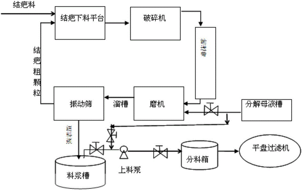
[0034] (2) Scar recovery treatment: use a crusher to crush the scars on the scraping platform to obtain scars with a particle size of ≤250mm. The crushed scars are sent to the ball mill through the conveyor belt and pumped into the ball mill The decomposing mother liquor is ball milled, and the volume...

Embodiment 2

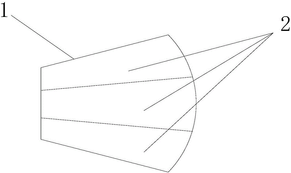
[0039] The recovery method and recovery system are the same as the recovery system of Example 1, and the inventive concept is the same. The difference is: the volume ratio of scarring to decomposition mother liquor is 1:3, and the decomposition mother liquor is introduced at the inlet of the feeding pump to adjust the solidity of the slurry. The content ratio is 700g / l, and the fan-shaped chute is divided into 5 fan-shaped guide grooves by the partition; the feeding pump and the hydraulic pump are gear pumps and the flow rate is 35m 3 / h, the output pressure is 0.8Mpa; the distance between the control valve and the feeding pump is 3m.


PUM

PropertyMeasurementUnit
Particle sizeaaaaaaaaaa

Abstract

The invention discloses a decomposing tank scab cleaning and recovery method and a system thereof. The decomposing tank scab cleaning and recovery method comprises the following steps of (1) cleaning scabs manually, and (2) recovering and treating the scabs. The system comprises a scab discharging platform, a crusher, a ball mill, a vibrating screen, a slurry tank, a decomposing mother liquor tank, a distributing box and a flat plate filter, wherein the scab discharging platform is connected with the crusher through a conveying belt; the crusher is connected with the ball mill through the conveying belt; the ball mill is connected with the vibrating screen through a chute; the vibrating screen is connected with the scab discharging platform through the conveying belt; the slurry tank is arranged at the bottom of the vibrating screen, and is connected with the distributing box through a connecting pipeline; a charging pump is arranged on the connecting pipeline; the distributing box is connected with the flat plate filter; the decomposing mother liquor tank is connected with inlets of the ball mill and the charging pump through the hydraulic pipelines respectively; and hydraulic pumps are arranged on the hydraulic pipelines. The decomposing tank scab cleaning and recovery method and the system are reasonable in design, low in cost, and high in recovery rate, and have popularization values.

Description

【Technical Field】 [0001] The invention belongs to the field of alumina production, and particularly relates to a method and a system for cleaning and recovering scars in a decomposition tank. 【Background technique】 [0002] The seed decomposition process in alumina production uses a large flat-bottomed mechanical stirring decomposition tank as the decomposition equipment. Due to the dead corner of the tank at the bottom of the tank, the low stirring speed and high solid content, the stirring itself also has design defects, so the decomposition tank runs during the operation process In the bottom of the tank, a large amount of aluminum hydroxide is gradually deposited and formed scars about 2 meters high. The height of the scars around the tank can even reach 3-5 meters. The total amount of scars is more than 500 tons. The approach to the stirring blade will cause the stirring load to increase, or the stirring blade will be rubbed or even crushed to death, which seriously affects ...

Claims


Application Information

Patent Timeline
IPC IPC(8): B02C21/00B02C23/08B02C23/16B09B3/00B09B5/00C01F7/02
CPCB02C21/00B02C23/08B02C23/16B02C2023/165B09B3/00B09B5/00C01F7/02
Inventor 赵志强
Owner 广西田东锦鑫化工有限公司
Why Eureka
Try Eureka