Pouring system for casting diesel engine block casting

A pouring system, diesel engine technology, applied in casting molding equipment, casting molds, casting mold components, etc., can solve the problems of not easy to fill the molten metal, easy oxidation of molten metal, small metal oxidation, etc., to avoid inclusion defects, reduce surface The effect of oxidation and metal cleaning

Inactive Publication Date: 2016-11-09
四川共享铸造有限公司
View PDF8 Cites 6 Cited by
  • Summary
  • Abstract
  • Description
  • Claims
  • Application Information

AI Technical Summary

Problems solved by technology

The characteristics of the open gating system are that the filling is stable, the scouring force on the cavity is small, but the ability to retain slag is poor. When the opening ratio of each component is large, the molten metal is not easy to fill the gating system, and it is in a pressureless flow state; bottom injection The characteristics of the type pouring system are that the molten metal enters the mold cavity smoothly, the impact force on the mold and the core is small, and the metal oxidation is small, which is conducive to the discharge of gas in the cavity, but the consumption of molten metal is large, which is not conducive to feeding, and the surface of the molten metal is prone to oxidation Skin
[0003] The gating system of traditional diesel engine body castings is an open and bottom pouring gating system. The runners are usually composed of two or more runners, which are arranged along the space around the casting. Usually, 6 to 14 inner runners are evenly distributed. The shape and size ratio of the runners are the same, so the gating system has complex structure and large size, the molten metal is easy to oxidize, castings are prone to defects such as inclusions, sand inclusions, and shrinkage porosity, and the yield is low

Method used


Image

  • Pouring system for casting diesel engine block casting
  • Pouring system for casting diesel engine block casting
  • Pouring system for casting diesel engine block casting

Examples


Embodiment Construction

[0019] In order to enable those skilled in the art to better understand the technical solutions of the present invention, the present invention will be further described in detail below in conjunction with specific embodiments.

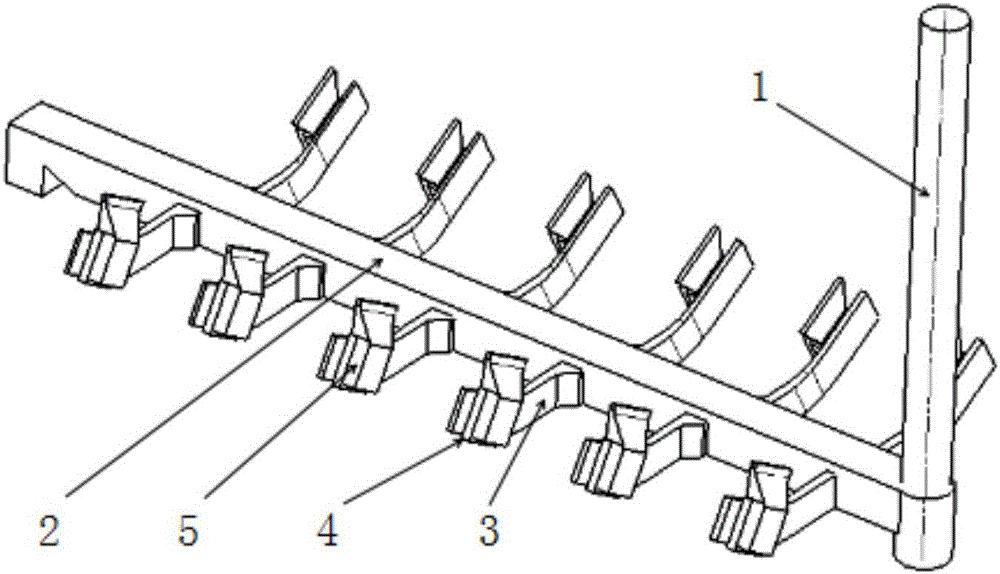
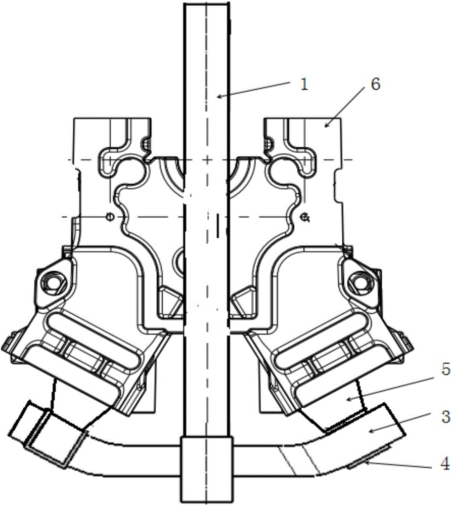
[0020] see figure 1 , figure 2 , the present invention provides a pouring system for casting diesel engine block castings, which includes a sprue 1, a runner 2, twelve inrunners A3 and twelve inrunners B5, direct pouring The outlet of channel 1 is vertically connected with the inlet of runner 2, and the ingate A3 is arranged symmetrically on both sides of runner 2, the outlet of ingate A3 is connected to the filter device 4, and the filter device 4 is connected to the ingate B5 connected, the height of the gate of the inrunner B 5 is higher than that of the runner 2, and the molten metal flows into the mold 6 of the diesel engine body from the gate of the inrunner B 5 for casting; the cross-sectional area of ​​the sprue 1 is smaller than that of the...


PUM


Abstract

The invention discloses a pouring system for casting a diesel engine block casting. The pouring system comprises a sprue, a cross gate and a plurality of ingates A and ingates B, wherein an outlet of the sprue is perpendicularly connected with an inlet of the cross gate; the ingates A are symmetrically arranged on two sides of the cross gate in a spacing manner; outlets of the ingates A are connected with filtering devices; the filtering devices are connected with the ingates B; the heights of the pouring gates of the ingates B are greater than that of the cross gate; the sectional area of the sprue is smaller than that of the cross gate; the sectional area of the cross gate is smaller than the total of the sectional areas of the ingates A and the sectional areas of the ingates B; the sectional area of each of the ingates A is smaller than that of each ingate B; and the sectional areas of the ingates A are gradually decreased along the direction from the inlet and the outlet of the cross gate. The pouring system for casting the diesel engine block casting can effectively prevent oxidization of molten metal and relieve scouring to a casting mold; and the yield of the casting is greatly increased, and the pouring system is applicable to casting of large-size iron castings such as the diesel engine block casting.

Description

technical field [0001] The invention relates to a gating system, in particular to a gating system for casting diesel engine body castings, and belongs to the technical field of casting. Background technique [0002] In casting technology, the gating system refers to the channel that introduces liquid metal into the mold cavity. Its functions are: 1. Control the speed of filling the mold with molten metal and the time required to fill the mold; 2. Make the molten metal stable 3. Prevent slag and other inclusions from entering the mold cavity; 4. Do not get involved in gas during pouring, and try to make the casting conform to the principle of sequential solidification when cooling. Existing gating systems generally include sprues, runners and ingates, which can be divided into closed, semi-closed and open gating systems according to the proportion of each component section; The injection position is divided into top injection, middle injection, bottom injection and layered i...

Claims


Application Information

Patent Timeline
Patent Type & Authority Applications(China)
IPC IPC(8): B22C9/08B22C9/22
CPCB22C9/082B22C9/086B22C9/22
Inventor 李小静
Owner 四川共享铸造有限公司
Why Eureka
Try Eureka