
A ladle baking table

A baking table and ladle technology, which is applied in metal processing equipment, manufacturing tools, casting molten material containers, etc., can solve the problems of waste of heat energy, amazing energy waste, and insufficient utilization of heat energy in ladle baking

Active Publication Date: 2020-07-07
边仁杰
View PDF6 Cites 0 Cited by
  • Summary
  • Abstract
  • Description
  • Claims
  • Application Information

AI Technical Summary

Problems solved by technology

[0002] Most of the existing ladle baking energy waste is astonishing
Thermal calculations show that the heat utilization rate of ladle baking is less than 2%, and more than 98% of heat energy is wasted
Although the invention of ZL200910120000.4 is a good way to save energy by thermal energy ladder utilization, it is not suitable for most steel enterprises. At present, most steel enterprises urgently need to implement a simple and easy series baking method for brick ladles to realize thermal energy ladder utilization and energy saving. Reduce consumption and maintain low-cost production

Method used


Image

  • A ladle baking table
  • A ladle baking table
  • A ladle baking table

Examples


Embodiment Construction

[0024] The present invention will be described in further detail below in conjunction with the accompanying drawings and specific embodiments.

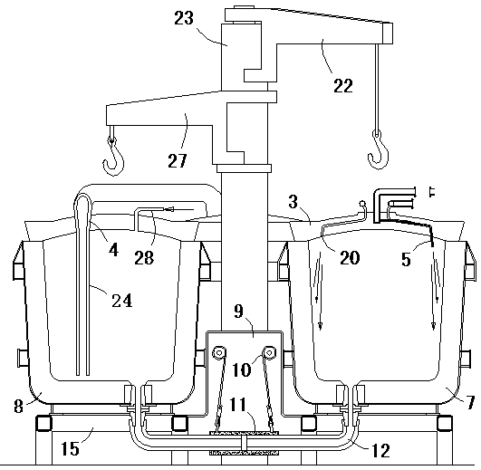
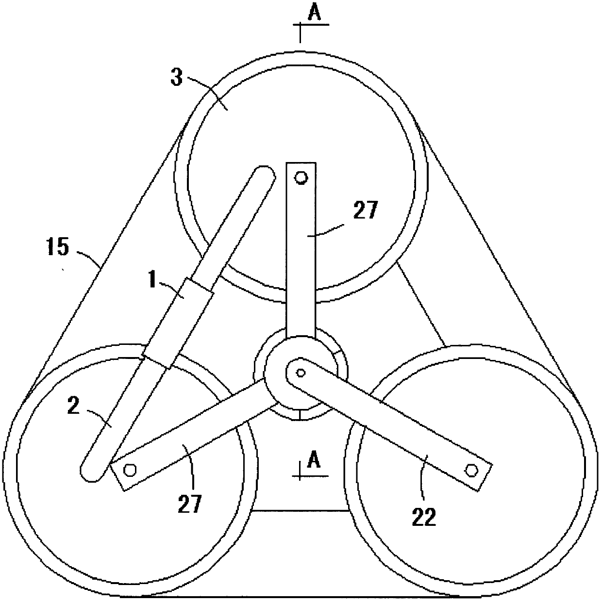
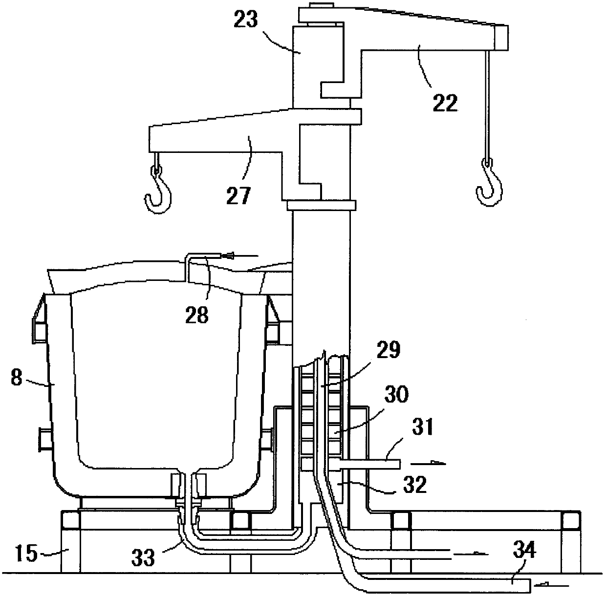
[0025] attached Figure 1-3 Shown is one concept of the general structure of the invention.

[0026]As shown in the figure, the hanging column 23 of the cantilever crane is provided with a single cantilever crane 22 and a double cantilever crane 27, the single cantilever crane 22 is used to lift the bag cover 3 of the fire baked bun 7, and the bag cover 3 rotates and shifts out Hanging out or hanging into the lifting space of the fire baking bag 7, the double cantilever crane 27 is used to lift the bag cover 3 of the hot baking bag 8, and the rotation and displacement give way to the lifting space of hanging out or hanging in; the single cantilever crane 22 is also used The standpipe 24 is lifted so that the double cantilever crane 27 can lift the cover 3 of the hot baking bag 8 to rotate and shift; A nozzle 20 is provided, and the ...


PUM


Abstract

The invention relates to metallurgy pouring ladle baking. A hanging column (23) of a cantilever sling is provided with a single-cantilever sling (22) and a double-cantilever sling (27). The single-cantilever sling (22) is used for hoisting a ladle cover (3) of a fire baking ladle (7). The ladle cover (3) rotates and moves to provide hoisting space for the fire baking ladle (7) to be hoisted out or in. The double-cantilever sling (27) is used for hoisting a ladle cover (3) of a heat baking ladle (8) and rotates and moves to provide hoisting space for hoisting out or in. The single-cantilever sling (22) is also used for hoisting a stand pipe (24), and therefore the double-cantilever sling (27) can hoist the ladle cover (3) of the heat baking ladle (8) for rotation and displacement. A heat flow pipe (12) is connected with the fire baking ladle (7) and the heat baking ladle (8). The ladle cover (3) of the fire baking ladle (7) is provided with a spraying port (20) spraying oxygen to assist in combustion of fuel gas sprayed by a spraying pipe (5), flame heat flow flows into the heat flow pipe (12) through a water port hole or a seat brick hole and flows into a water port hole of the heat baking ladle (8) through the heat flow pipe (12) to bake the heat baking ladle (8).

Description

technical field [0001] The invention relates to metallurgical ladle baking, especially steel ladle baking. . Background technique [0002] The vast majority of existing ladle baking energy wastes are astonishing. Thermal calculations show that the heat utilization rate of ladle baking is less than 2%, and more than 98% of heat energy is wasted. For example: a 100t steel ladle is about 9000Kg of refractory materials, and the newly built 100t steel ladle needs to be baked for 80-100 hours before it can be used, and the average baking time is about 4.5m per minute. 3 Calorific value is 9196KJ / m 3 Gas or converter gas, a total of about 21600 m 3 Gas, 21600 m 3 Gas is about 198635600 kJ heat energy, equivalent to 6777.7Kg standard coal. For a ladle of 10000 kg refractory material, the inner surface is baked to 100°C, and the outer surface reaches the applicable standard of 170°C. At this time, the specific heat capacity of the refractory material is calculated as 0.74kJ / kg:...

Claims


Application Information

Patent Timeline
Patent Type & Authority Patents(China)
IPC IPC(8): B22D41/015
CPCB22D41/015
Inventor 边仁杰
Owner 边仁杰
Learn More