Finger transmission device of multi-joint robot

A multi-joint robot and transmission device technology, applied in the field of robotics, can solve the problem of less movement of the finger structure of space-driven robots

Inactive Publication Date: 2016-11-09
BEIJING LINGYI TECH CO LTD
View PDF3 Cites 2 Cited by
  • Summary
  • Abstract
  • Description
  • Claims
  • Application Information

AI Technical Summary

Problems solved by technology

Efficiently solves the problem of empty travel and less movement of the robot finger structure when the m

Method used


Image

  • Finger transmission device of multi-joint robot
  • Finger transmission device of multi-joint robot
  • Finger transmission device of multi-joint robot

Examples


Embodiment Construction

[0016] The specific implementation of the present invention will be further described below in conjunction with the accompanying drawings and examples. The following examples are only used to illustrate the technical solutions of the present invention more clearly, but not to limit the protection scope of the present invention.

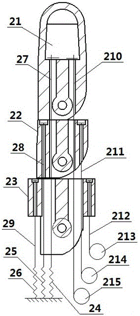
[0017] like figure 2 and image 3 As shown, the technical solution of the present invention is to design a multi-joint robot finger transmission device, including a first finger joint 21, a second finger joint 22, a third finger joint 23, a return spring one 24, a return spring two 25, and a return spring Three 26, rebound rope one 27, rebound rope two 28, rebound rope three 29, tension rope one 210, tension rope two 211, tension rope three 212, motor output disk one 213, motor output disk two 214 And motor output disc three 215.

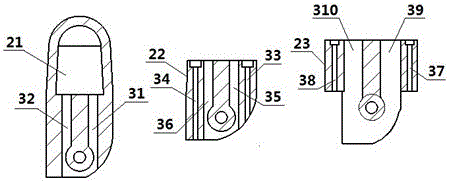
[0018] The first knuckle 21 has a mounting groove 31 for the tension rope 1 of the first knuckle and a mounting groove...


PUM


Abstract

The invention belongs to the field of robots, and relates to a finger transmission device of a multi-joint robot. The finger transmission device comprises a first knuckle, a second knuckle, a third knuckle, a reset spring I, a reset spring II, a reset spring III, a springback rope I, a springback rope II, a springback rope III, a tension rope I, a tension rope II, a tension rope III, a motor output tray I, a motor output tray II and a motor output tray III. According to the finger transmission device, springback rope and tension rope mounting grooves are additionally formed in the three knuckles, so that the three springback ropes and the three tension ropes are positioned in the three knuckles and are completely limited. The three reset springs are arranged, so that the pull direction of the three reset springs is collinear with the movement direction of the three springback ropes. By adopting the principle, the three springback ropes cannot be loose. The idle stroke of a motor does not exist when robot fingers are controlled to bend and straighten. The three springback ropes and the three tension ropes are respectively used for controlling the three knuckles, so that a robot finger structure is operated in various manners.

Description

technical field [0001] The invention belongs to the field of robots, and relates to a multi-joint robot finger transmission device. Background technique [0002] With the improvement of people's living standards and the continuous increase of demand, various intelligent devices gradually appear. The pinnacle product of the so-called intelligent equipment of robots has helped people from all walks of life and solved many problems. The structure of the robot hand, the so-called important part of the robot to grab objects, is a problem that many structural engineers need to overcome. like figure 1 As shown, the existing robot hand structure includes, the existing first knuckle 1, the existing second knuckle 2, the existing third knuckle 3, the existing return spring one 4, the existing return spring two 5, the existing Rebound rope 6, existing tension rope 7 and existing motor output disk 8 are arranged. Its principle is that when the existing motor output disc 8 rotates co...

Claims


Application Information

Patent Timeline
IPC IPC(8): B25J15/00
CPCB25J15/0009
Inventor 王彦君张雅晨
Owner BEIJING LINGYI TECH CO LTD
Why Eureka
Try Eureka