Suspension type high-frequency vibration method and special device

A vibrating device and suspended technology, which is applied in the field of suspended high-frequency vibrating devices, can solve problems such as low flatness, inability to realize automatic continuous operation, and low efficiency, and achieve the goal of improving flatness, realizing automatic continuous operation, and improving efficiency Effect

Active Publication Date: 2016-11-09
HUNAN ZHONGLU HUACHENG BRIDGE TECH CO LTD
View PDF7 Cites 7 Cited by
  • Summary
  • Abstract
  • Description
  • Claims
  • Application Information

AI Technical Summary

Problems solved by technology

Ordinary high-frequency vibrating devices have to be manually operated, which is inefficient and has low flatness, and cannot realize automatic continuous operation

Method used


Image

  • Suspension type high-frequency vibration method and special device
  • Suspension type high-frequency vibration method and special device
  • Suspension type high-frequency vibration method and special device

Examples


Embodiment 1

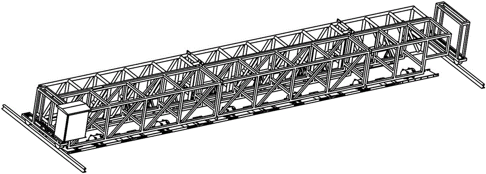
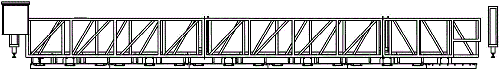
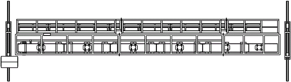
[0028] Embodiment 1, refer to Figure 1 to Figure 5 . The suspended high-frequency vibrating device includes a vibrating truss 25, a vibrating and leveling device 28 and a suspended high-frequency vibrating device 22. The two ends of the vibrating truss 25 are respectively equipped with a vibrating and leveling device 28. Suspended high-frequency vibrating device 22 is installed; said suspended high-frequency vibrating device 22 includes more than 2 vibrating flat plates 222, and high-frequency vibrating motors 221 are respectively installed on each vibrating flat plate 222, and each vibrating flat plate 222 adopts an elastic suspension device 223 is installed under the vibrating truss 25, and each high-frequency vibration motor 221 drives each vibrating plate 222 to vibrate up and down; when the cloth machine finishes laying a preset length of vertical cloth, the vibration leveling intelligent control device instructs to start the suspension type The high-frequency vibrating...

Embodiment 2

[0032] In Embodiment 2, the present invention may also provide a vibration damping device 225 between the elastic suspension device 223 and the vibrating plate 222 , so as to buffer the vibration of the vibrating truss 25 . refer to Figure 1 to Figure 5 , all the other are with embodiment 1.

Embodiment 3

[0033]Embodiment 3, the present invention may also be provided with a vibrating leveling intelligent control device 26 matched with a high-frequency vibration motor 221 on the vibrating truss 25, and the vibrating leveling intelligent control device 26 may also be installed on the vibrating leveling On the leveling walking device 28, in order to reduce the influence of vibration on the leveling intelligent control device 26 due to vibration, preferably the vibration leveling intelligent control device 26 is installed on the vibration leveling leveling device 28, so that Realize automatic control with other systems. For example, after the precision cloth machine finishes laying out the predetermined length of longitudinal cloth, the suspension type high-frequency vibrating device is started to vibrate through the command issued by the vibration leveling intelligent control device, and the longitudinal walking device moves forward at the preset speed to realize high-frequency vib...


PUM

PropertyMeasurementUnit
lengthaaaaaaaaaa

Abstract

The invention provides a suspension type high-frequency vibration method and a special device. The technical problem that reactive powder concrete needs to be vibrated and leveled repeatedly is mainly solved through the suspension type high-frequency vibration method and the special device. According to the technical scheme, the suspension type high-frequency vibration method and the special device are characterized in that vibration leveling walking devices (28) are installed at the two ends of a vibration truss (25) correspondingly; a suspension type high-frequency vibration device body (22) is installed on the lower portion of the vibration truss (25) and comprises two or more vibration flat plates (222); and a vibration flat plate oblique angle adjusting device (224) is installed on each elastic suspension device (223) in a matched mode, so that an 1-70 degree included angle is formed between each vibration flat plate (222) and the horizontal plane. According to the suspension type high-frequency vibration method and the special device, due to the fact that manual operation is not needed, the efficiency is greatly improved, the leveling effect is better, the leveling degree is also greatly improved, and automatic continuous operation is achieved. The suspension type high-frequency vibration method and the special device are mainly used in the field of reactive powder concrete production construction and the like.

Description

technical field [0001] The invention relates to a concrete paving machine, in particular to a suspended high-frequency vibrating device. Background technique [0002] At present, due to the shortcomings of ordinary concrete such as low tensile strength, poor toughness, and crack development after cracking, the premature deterioration of concrete structures cannot continue to be used, and the durability and service life of important concrete structures have also been greatly reduced. . In order to overcome these shortcomings of concrete, ultra-high toughness cement-based composite (ECC) was proposed to be applied to concrete. Optimized, and add 2%~3.5% volume ratio of fiber. The concrete made of this kind of ultra-high toughness cement-based composite material can significantly improve the tensile strength and shear resistance of concrete. Therefore, the good toughness of this kind of concrete can effectively control the development of concrete cracks. It has been successfu...

Claims


Application Information

Patent Timeline
Patent Type & Authority Applications(China)
IPC IPC(8): B28B1/04B28B1/08B28B1/52
CPCB28B1/045B28B1/08B28B1/523Y02A30/30
Inventor 彭力军李沧谢方生谭志李亚波康大桥许友
Owner HUNAN ZHONGLU HUACHENG BRIDGE TECH CO LTD
Why Eureka
Try Eureka