Pneumatic braking control unit for railway vehicles

A rail vehicle and control unit technology, applied in the field of rail transit, can solve the problems of unsafe, relay valve losing the ability to output braking pressure, increase system safety redundancy, etc., and achieve high maintainability and high interchangeability Effect

Inactive Publication Date: 2016-11-09
海幄控制技术(上海)有限公司
View PDF8 Cites 9 Cited by
  • Summary
  • Abstract
  • Description
  • Claims
  • Application Information

AI Technical Summary

Problems solved by technology

[0004] The Chinese invention patent with the patent publication number CN 103010251 A discloses a brake control unit for high-speed EMUs and urban rail transit vehicles, including EP (pilot valve) valves, emergency valves, empty-load vehicle valves and relay valves, which can The proportional output of the brake cylinder pressure is realized, and the valves are connected by internal pipelines. The internal pipelines are integrated on the bottom plate of the air circuit, which has high interchangeability and maintainability, but it has the following disadvantages: it is a single The output mode of the brake cylinder pressure does not satisfy the function of outputting different brake cylinder pressures under different working conditions for EMUs; there is no relay valve fault backup function, because the relay valve is a frequently moving part, once it fails, it will seriously affect the The operation safety of the train, such as the diaphragm of the pre-control signal pressure chamber is damaged or broken, and the relay valve loses the ability to output brake pressure; when there is no relay valve failure or other reasons cause the pressure of the brake cylinder cannot be relieved, manual operation is required. The relief of the brake cylinder is inconvenient and unsafe to operate; without the backup function of the emergency valve, the above-mentioned brake control unit will lose all the brake control pressure when the emergency valve fails, which poses a great threat to the operation safety of the vehicle
[0005] The Chinese invention patent with the patent publication number of CN 104260745 A discloses a brake control unit for EMUs, which includes an air brake control unit and an electronic brake control unit integrated in the same brake cabinet. The relay valve adopts dual pre-control relay valves, the EP valve module is connected to the common brake pre-control pressure port, and the emergency valve is connected to the emergency brake pre-control pressure port, which increases the safety redundancy of the system, and also adopts remote forced relief function, when the forced release operation is required, the pressure of the brake cylinder can be directly relieved remotely through the switch set on the train, which effectively reduces the operation complexity of the system and improves the maintainability of the system, but it still has the following disadvantages: no emergency Valve backup function, the brake control unit above will lose all brake control pressure when the emergency valve fails, which poses a great threat to the safety of the vehicle; there is no backup when the pre-control pressure of the relay valve drops sharply or disappears Function, this function is a safety redundancy function, this safety redundancy function is manifested in: in one case, when the pressure of the relay valve pre-control signal pressure pipeline drops to zero rapidly, the relay valve still has pressure output to ensure the basic safety of the train Braking function, another situation is that the diaphragm of the pre-control signal pressure chamber of the relay valve is damaged or broken, the pre-control pressure is directly and quickly discharged into the atmosphere, and the relay valve still has pressure output to ensure the basic braking function of the train; In the case of direct electropneumatic brake control failure, the function of using the pressure interface of indirect control reduces the safety redundancy of the system

Method used


Image

  • Pneumatic braking control unit for railway vehicles
  • Pneumatic braking control unit for railway vehicles

Examples


Embodiment Construction

[0023]The present invention will be described in detail below in conjunction with specific embodiments. The following examples will help those skilled in the art to further understand the present invention, but do not limit the present invention in any form. It should be noted that those skilled in the art can make several modifications and improvements without departing from the concept of the present invention. These all belong to the protection scope of the present invention.

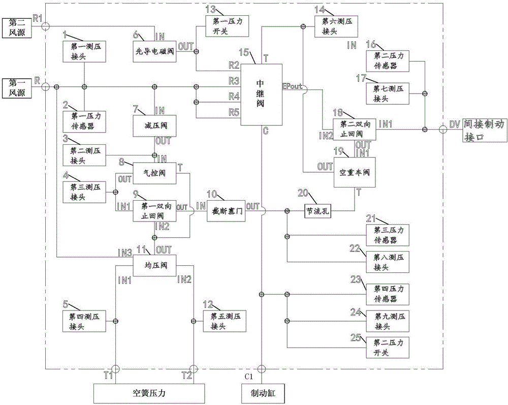
[0024] The rail vehicle air brake control unit of the present invention comprises:

[0025] A plurality of pressure measuring joints are placed on the pipeline of the gas circuit bottom plate to detect the pressure in the corresponding pipeline;

[0026] A plurality of pressure sensors are all placed on the pipeline of the gas channel bottom plate, and are used to convert the pressure signal in the corresponding pipeline into an electrical signal and output it;

[0027] A plurality of pressure swi...


PUM


Abstract

The invention provides a pneumatic braking control unit for railway vehicles. The pneumatic braking control unit for railway vehicles comprises nine pressure detection connectors, four pressure sensors, two pressure switches and a relay valve, wherein the nine pressure detection connectors are used for detecting the pressures in corresponding pipelines; the four pressure sensors are used for converting pressure signals in the corresponding pipelines into electric signals and outputting the electric signals; the two pressure switches are used for carrying out detection, displaying, alarming and control output on the pressures in the pipelines so that the normal operation of the whole pneumatic braking control unit for railway vehicles can be ensured; and the relay valve is used for controlling air exhausting or air inflation according to the internal pressure change. The pneumatic braking control unit for railway vehicles is high in degree of integration, high in control precision and good in stability, the safety performance index and the maintainability index of a braking system are increased, and meanwhile the system safety is high.

Description

technical field [0001] The invention relates to the field of rail transportation, in particular to an air brake control unit for rail vehicles. Background technique [0002] The pneumatic brake control unit is a core module of the rail vehicle braking system, especially the pneumatic control core component of the urban rail vehicle and EMU train braking system. Its main function is to convert the braking command into the corresponding braking pressure. Control to unit brake for brake release. [0003] Pneumatic brake control unit is an electric and pneumatic logic control module, its performance directly determines whether the brake control system can realize the control of braking force stably, accurately and reliably, and plays a vital role in the safety of train operation. [0004] The Chinese invention patent with the patent publication number CN 103010251 A discloses a brake control unit for high-speed EMUs and urban rail transit vehicles, including EP (pilot valve) va...

Claims


Application Information

Patent Timeline
Patent Type & Authority Applications(China)
IPC IPC(8): B61H11/06
CPCB61H11/06
Inventor 吴兴东
Owner 海幄控制技术(上海)有限公司
Why Eureka
Try Eureka