
Planar three-range-of-motion loading robot with multi-unit connection rod driving function

A link-driven, three-degree-of-motion technology, which is applied to mechanically driven excavators/dredgers, earth movers/shovels, construction, etc., can solve the problem of lack of overload protection and vibration absorption means, and poor stability of the boom lifting mechanism , poor power performance and other problems, to achieve the effect of realizing numerical control of operations, strong overload protection performance, and reducing energy consumption

Inactive Publication Date: 2016-11-09
SHANDONG JIAOTONG UNIV
View PDF5 Cites 2 Cited by
  • Summary
  • Abstract
  • Description
  • Claims
  • Application Information

AI Technical Summary

Problems solved by technology

[0004] The purpose of the present invention is to provide a multi-unit link-driven plane three-movement loading robot, which has the advantages of high intelligence, good flexibility, and high transmission efficiency of the existing controllable loading mechanism, and solves the problems existing in the prior art. The existing controllable loading mechanism has engineering problems such as poor dynamic performance, weak load capacity, poor stability of the boom lifting mechanism, lack of effective overload protection and vibration absorption means, so that the loading robot has good dynamic performance and load stability. Has strong anti-vibration ability and overload protection performance

Method used


Image

  • Planar three-range-of-motion loading robot with multi-unit connection rod driving function
  • Planar three-range-of-motion loading robot with multi-unit connection rod driving function
  • Planar three-range-of-motion loading robot with multi-unit connection rod driving function

Examples


Embodiment Construction

[0027] The technical solutions of the present invention will be further described below through the accompanying drawings and embodiments.

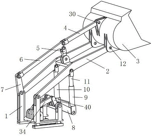
[0028] control figure 1 , a multi-unit link-driven planar three-movement loading robot according to the present invention includes a multi-unit link drive mechanism, a boom lifting mechanism, a bucket control mechanism and a frame 1 .

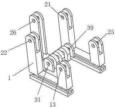
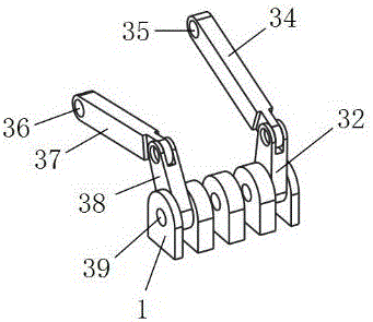
[0029] control figure 1 , figure 2 , image 3 , Figure 4 , Figure 5 , the multi-unit connecting rod drive mechanism includes a frame 1, a first active rod 32, a second active rod 38, a first connecting rod 34, a second connecting rod 37, and a crankshaft 40, and one end of the first active rod 32 passes through The first rotating pair 31 is connected to the frame 1, and the other end is connected to one end of the first connecting rod 34 through the second rotating pair 33, and the other end of the first connecting rod 34 is connected to the crankshaft 40 through the third rotating pair 35. One en...


PUM


Abstract

A planar three-range-of-motion loading robot with a multi-unit connection rod driving function comprises a multi-unit connection rod driving mechanism, a movable arm lifting mechanism, a fork bucket control mechanism and the like. Under control of a computer, the multi-unit connection rod driving mechanism achieves driving of multiple small-power motors and high-power and high-torque power output, and meets the power requirement of high-load operation of the slippage type loading robot. On the basis of the Pascal principle, a hydraulic element is introduced to the movable arm lifting mechanism, equal in-cylinder pressure is achieved, the problem that stress on two driving chains for driving a movable arm of an original controllable loading mechanism is unbalanced is effectively solved, and the bearing stability is improved. The loading robot has the characteristics of being high in transmission efficiency, high in response speed, high in motion precision, good in controllability and the like as the original controllable loading mechanism, but also has better bearing performance and vibration resistance through introduction of the multi-unit connection rod driving mechanism and the hydraulic element, can achieve the overload protection function easily, and is quite suitable for manufacturing of large, intermediate and small-sized loading robots.

Description

technical field [0001] The invention relates to the field of loaders, in particular to a multi-unit link-driven plane three-movement loading robot. Background technique [0002] Loader is a key equipment widely used in farmland, water conservancy, energy, municipal and other construction fields for bulk material loading and unloading, which plays an important role in infrastructure construction. However, traditional hydraulic loaders have high energy consumption and noise. Large, serious exhaust emissions, low level of intelligence and other shortcomings. The controllable mechanism is the product of the combination of traditional mechanism and electronic technology. The "Numerical Control Generation" equipment innovation project carried out in recent years has brought opportunities for the upgrading of traditional construction machinery technology. Aiming at the shortcomings of hydraulic loaders, the controllable mechanism and robot The relevant technology is applied to the...

Claims


Application Information

Patent Timeline
Patent Type & Authority Applications(China)
IPC IPC(8): E02F3/34E02F3/42E02F3/43
CPCE02F3/3414E02F3/3405E02F3/422E02F3/431
Inventor 张林母建鑫
Owner SHANDONG JIAOTONG UNIV
Learn More