Friction-mild steel composite damper

A composite, damper technology, applied in the field of dampers, can solve problems such as difficulty in determining the sliding friction force, and achieve the effect of protecting the safety of the structure, reducing the dynamic response and the accumulation of damage

Active Publication Date: 2016-11-09
HUAQIAO UNIVERSITY +1
View PDF9 Cites 12 Cited by
  • Summary
  • Abstract
  • Description
  • Claims
  • Application Information

AI Technical Summary

Problems solved by technology

Due to the uncertainty of the earthquake action that the engineering structure may suffer during the service process, it is difficult to determine the appropriate sliding friction for these constant friction friction dampers in engineering applications.

Method used


Image

  • Friction-mild steel composite damper
  • Friction-mild steel composite damper
  • Friction-mild steel composite damper

Examples


Embodiment 1

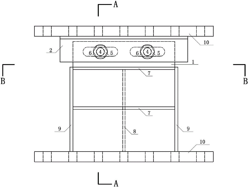
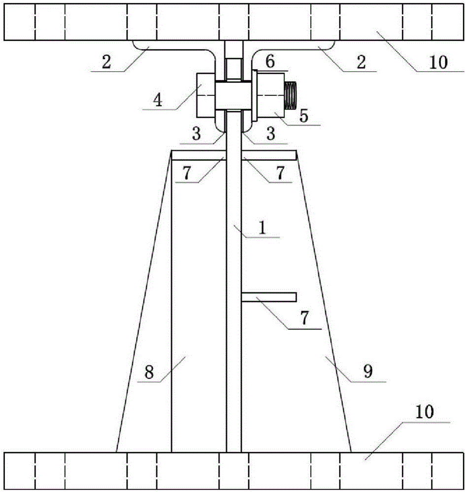
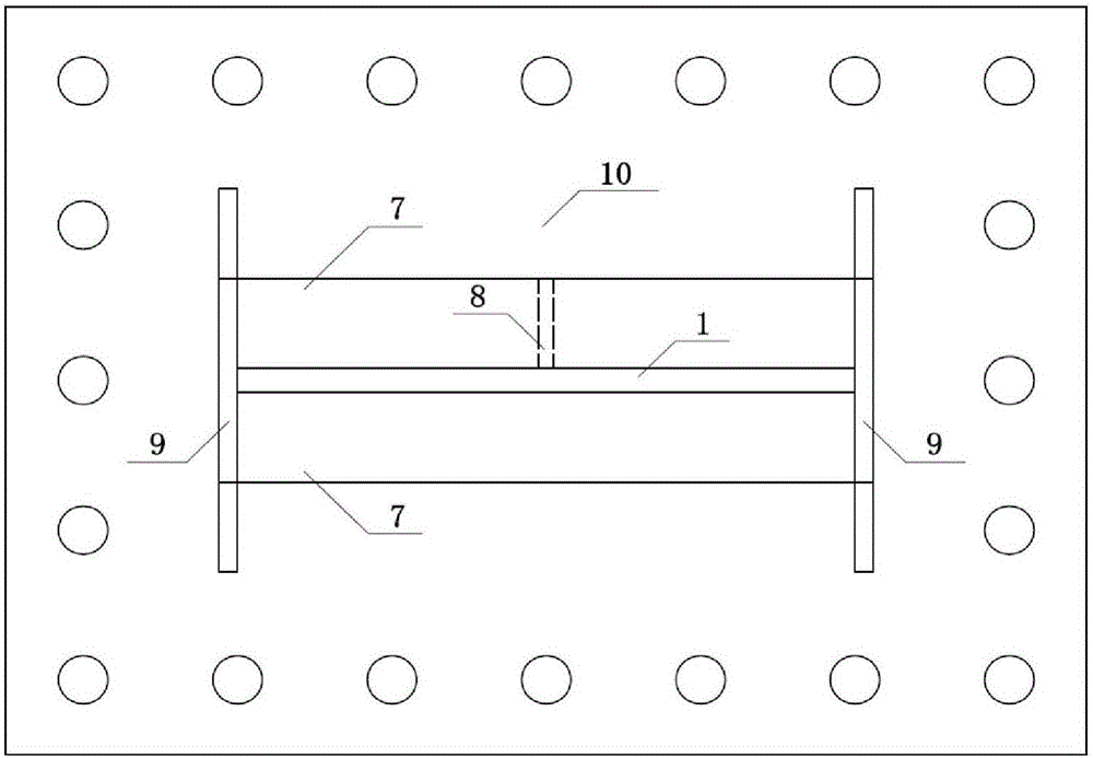
[0038] Such as figure 1 , figure 2 , image 3 As shown, the present invention includes a shearing energy-dissipating steel plate 1, an angle steel 2, and a friction plate 3. An angle steel 2 is installed on both sides of one end of the shearing energy-dissipating steel plate 1, and one side of the vertical direction of the angle steel 2 is connected to the shearing energy-dissipating steel plate 1. A friction plate 3 is installed between them, and the shearing energy-dissipating steel plate 1, the angle steel 2 and the friction plate 3 are connected and pre-tightened by the connection adjustment mechanism, thereby changing the sliding friction between the friction plate 3 and the shearing energy-dissipating steel plate 1 force.

[0039] In this embodiment, the connection adjustment mechanism includes a bolt 4, a nut 5, and a washer 6. For example, a high-strength bolt connection pair is formed by using a large hexagon head bolt 4, a large hexagon nut 5, and a washer 6, and ...

Embodiment 2

[0055] Such as Figure 10 As shown, in this embodiment, two groove-shaped holes are added on the shear energy-dissipating steel plate 1, and at the same time, a row of mounting holes is added on the angle steel 2 and the friction plate 3. Correspondingly, the gap between the three It is connected together by four sets of high-strength bolts.

[0056] Other parts are identical with embodiment 1.

[0057] The working principle of embodiment 2 is basically the same as that of embodiment 1. The difference is that the number of friction parts in embodiment 2 is increased compared with that of embodiment 1. Under the same loading conditions, the sliding friction force provided by embodiment 2 is theoretically higher than that of the actual embodiment. Example 1 is doubled. Therefore, Example 2 has stronger friction energy dissipation capacity than Example 1.


PUM

PropertyMeasurementUnit
yield strengthaaaaaaaaaa
elongationaaaaaaaaaa

Abstract

The invention relates to a friction-mild steel composite damper. The friction-mild steel composite damper comprises a shear energy dissipation steel plate, steel angles and a friction plate, wherein the steel angles are installed on the two sides of one end of the shear energy dissipation steel plate respectively, the friction plates are installed between one edge, in the vertical direction, of each steel angle and the shear energy dissipation steel plate, and the shear energy dissipation steel plate, the steel angles and the friction plates are connected and subjected to pretightening force adjustment through a connecting and adjusting mechanism so as to change the sliding friction force between the friction plates and the shear energy dissipation steel plate. The friction-mild steel composite damper is self-adaptive to the uncertainty of earthquake action, can achieve phased operation, is mainly used for energy dissipation and seismic mitigation of civil engineering structures, and can reduce dynamic response and damage accumulation of the engineering structures under earthquake action. When the friction-mild steel composite damper is installed between building structural layers or between a bridge structure box girder and a pier, the friction-mild steel composite damper can automatically select and execute a proper work mode under earthquake action with different intensity levels, so that the earthquake response of the structures is controlled and the safety of the structures is guaranteed.

Description

technical field [0001] The invention relates to a damper, more specifically, to a friction-mild steel composite damper. Background technique [0002] The traditional seismic design method is based on ensuring that the engineering structure has a certain strength, stiffness and ductility to resist the earthquake. However, due to the strong randomness of the time, location and intensity of earthquakes, the response state of engineering structures may fluctuate greatly, making it difficult to avoid entering a complex nonlinear stress state. Under the action of uncertain earthquake, the structure designed according to the traditional method, because its anti-seismic performance does not have the ability of self-regulation and control, may cause serious damage or even collapse due to failure to meet the safety requirements, resulting in casualties and economic losses. [0003] In order to further improve structural performance on the basis of traditional seismic design methods, ...

Claims


Application Information

Patent Timeline
Patent Type & Authority Applications(China)
IPC IPC(8): E04B1/98E04H9/02E01D19/00
CPCE01D19/00E04H9/021
Inventor 梅真郭子雄黄群贤刘阳曾宪敢陈昆明陈亚鹏
Owner HUAQIAO UNIVERSITY
Why Eureka
Try Eureka