
Fan device and machining method

A processing method and fan technology, applied to components of pumping devices for elastic fluids, non-variable pumps, machines/engines, etc., can solve the problem of difficult to ensure the bonding strength, concentricity and It is difficult to guarantee the balance and the bonding strength, etc., so as to save the casing material, improve the service life and achieve the effect of good concentricity

Inactive Publication Date: 2016-11-09
曾子斌
View PDF11 Cites 1 Cited by
  • Summary
  • Abstract
  • Description
  • Claims
  • Application Information

AI Technical Summary

Problems solved by technology

[0002] When the conventional motor fan is assembled, the rotor shaft is usually directly riveted into the rotor casing. Since the joint area between the rotor casing and the rotating shaft is small, the bonding strength is difficult to guarantee; and then the rotor casing riveted into the rotating shaft is pressed into the In the injection molding fan blade, the connection between the rotating shaft and the fan blade is realized by matching the size of the casing and the fan blade
This assembly method is difficult to ensure the bonding strength between the rotor shaft and the fan blades, as well as the concentricity and balance of the two. It is very noisy during use and affects the service life.

Method used


Image

  • Fan device and machining method
  • Fan device and machining method
  • Fan device and machining method

Examples


Embodiment Construction

[0020] The present invention will be described in further detail below in conjunction with the accompanying drawings.

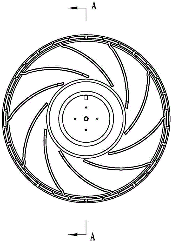
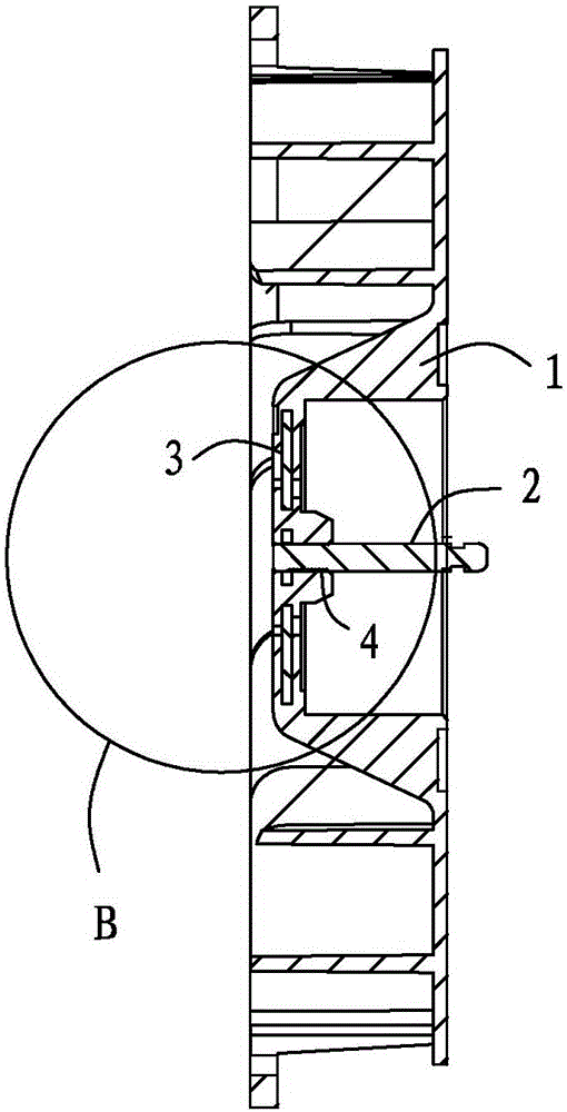
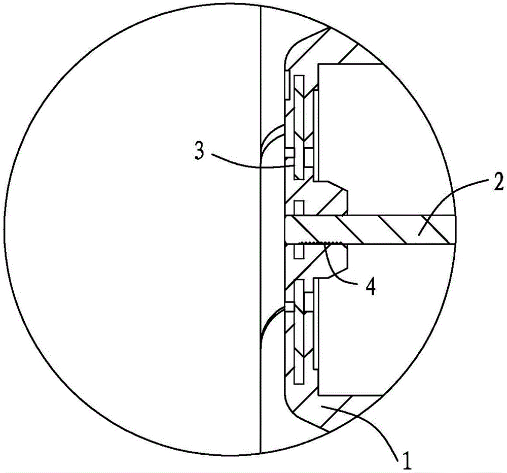
[0021] refer to figure 1 , figure 2 , image 3 and Figure 4 : Fan device, including fan blade 1, rotating shaft 2 and insert 3, one end of rotating shaft 2 is provided with knurling 4, fan blade 1 is sleeved on one end of rotating shaft 2, insert 3 is sleeved on the outside of rotating shaft 2, and embedded in Inside the fan blade 1. The knurling 4 at one end of the rotating shaft 2 has a pineapple-like pattern, which increases the tightness of the combination of the fan blade 1 and the injection molding at one end of the rotating shaft 2, and ensures the stability of the connection between the two.

[0022] Wherein, the fan blade 1 is an injection molded part, and the thickness of the insert 3 is 1-1.5 mm, preferably 1 mm.

[0023] The insert 3 is circular, and a round hole is arranged in the middle of the insert 3 , and the inner diameter of the roun...


PUM

PropertyMeasurementUnit
Thicknessaaaaaaaaaa

Abstract

The invention discloses a fan device. The fan device comprises fan blades, a rotary shaft and an insert, wherein knurls are formed in one end of the rotary shaft, the end of the rotary shaft is sleeved with the fan blades, the rotary shaft is sleeved with the insert, and the insert is inlaid in the fan blades. A machining method for the fan device comprises the following steps: (1) fixing one end of the rotary shaft and the insert in an injection mold after knurling the end of the rotary shaft; and (2) carrying out injection molding in the injection mold to obtain the fan blades through injection molding forming. Because one end of the rotary shaft and the insert are fixed in the injection mold, the perpendicularity between the rotary shaft and the insert can be revised through positioning of the mold; then the fan blades are obtained by carrying out injection molding forming in the injection mold so that the insert can be inlaid in the fan blades, it is guaranteed that one end of the rotary shaft is tightly fixed to the fan blades, and good concentricity is achieved; it is guaranteed that when the rotary shaft drives the fan blades to rotate, the stability is high, noise is reduced, and the service life is prolonged; and the manufacturing process is simple, the workload of a producer is reduced, and compared with the prior art, the materials of a machine case is saved, and the cost is reduced.

Description

technical field [0001] The invention belongs to a main component and a processing method of a motor fan, in particular to a fan device and a processing method. Background technique [0002] When the conventional motor fan is assembled, the rotor shaft is usually directly riveted into the rotor casing. Since the joint area between the rotor casing and the rotating shaft is small, the bonding strength is difficult to guarantee; and then the rotor casing riveted into the rotating shaft is pressed into the In the injection molding fan blade, the connection between the rotating shaft and the fan blade is realized by matching the size of the casing and the fan blade. This assembly method is difficult to ensure the bonding strength between the rotor shaft and the fan blades, and it is difficult to guarantee the concentricity and balance of the two. The noise is relatively large during use, and the service life is affected. Contents of the invention [0003] The object of the pre...

Claims


Application Information

Patent Timeline
IPC IPC(8): F04D29/26F04D29/053F04D29/66F04D29/02B29C45/78B29K67/00
CPCF04D29/26B29C45/78B29C2945/76531B29K2067/006F04D29/023F04D29/053F04D29/663F04D29/668
Inventor 曾子斌
Owner 曾子斌
Learn More