Synchronous running mechanism of hydraulic oil cylinder

A technology of synchronous operation and hydraulic cylinders, which is applied in the direction of mechanical equipment, fluid pressure actuators, servo motors, etc., and can solve the problems that cannot adapt to the narrow installation space of construction machinery, the synchronization of oil cylinders is not completely consistent, and the volume of oil cylinder assemblies is increased. , to ease the lifting action, prevent noise or vibration, and improve the lifting balance

Inactive Publication Date: 2016-11-09
昆山晋桦豹胶轮车制造股份有限公司
View PDF5 Cites 3 Cited by
  • Summary
  • Abstract
  • Description
  • Claims
  • Application Information

AI Technical Summary

Problems solved by technology

[0004] One is to mechanically connect the moving ends of all oil cylinders (such as the piston rod end or cylinder barrel end) to force the moving ends of the oil cylinders to run synchronously; however, when the moving ends of all oil cylinders are mechanically connected, the volume of the oil cylinder assembly is increased, making the oil cylinder The installation requires more space and cannot meet the requirements of the narrow installation space of construction machinery
[0005] The other is to install diverter valves at the oil inlets of all cylinders to control the amount of oil entering each cylinder to be roughly equal, so that the cylinders run synchronously; The exact same characteristics will also cause the cylinder synchronization to be inconsistent

Method used


Image

  • Synchronous running mechanism of hydraulic oil cylinder

Examples


Embodiment

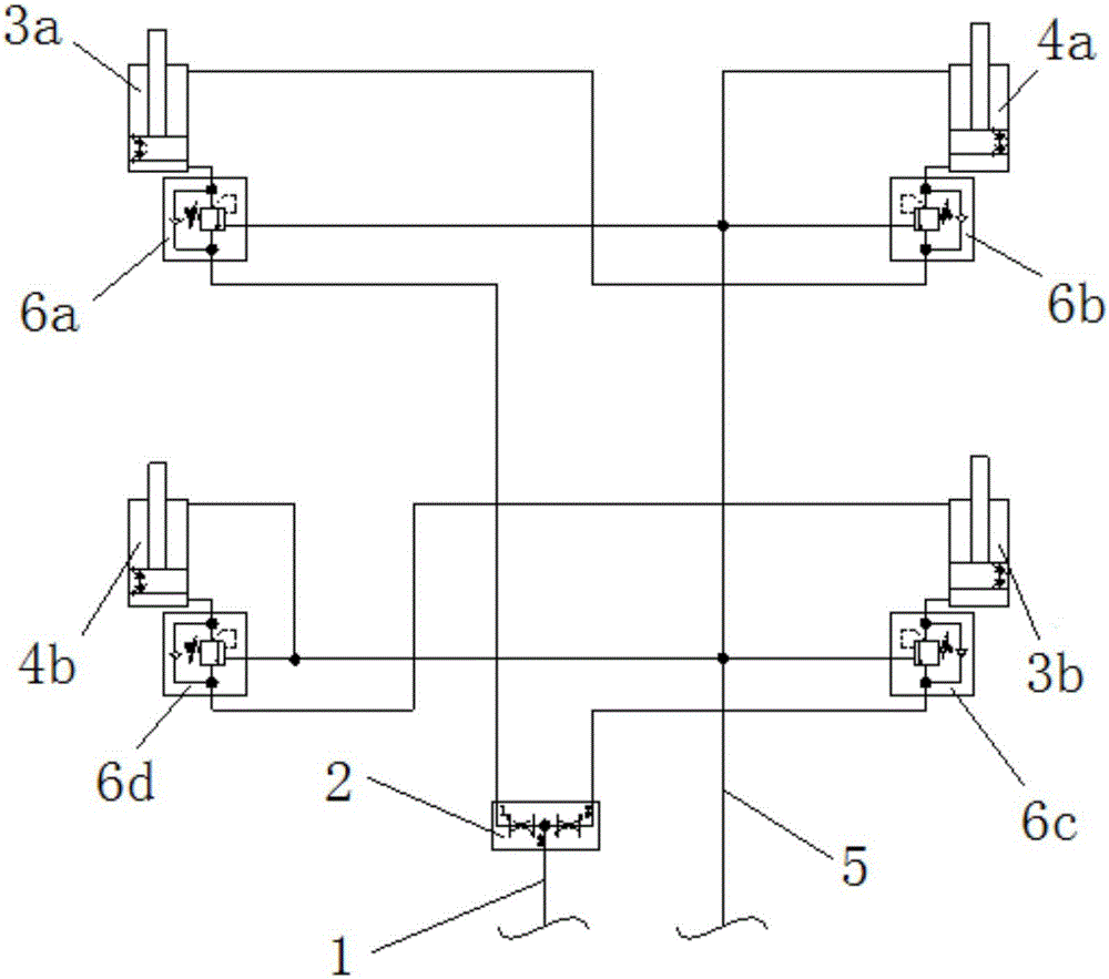
[0036] like figure 1 As shown, a hydraulic cylinder synchronous operation mechanism of the present invention includes a first oil pipe 1, and the first oil pipe 1 divides into two branches connected to the rodless cavity of the first active oil cylinder 3a and the rodless chamber of the second active oil cylinder 3b respectively. Rod chamber, the rod chamber of the first active cylinder 3a is connected to the rodless chamber of the first slave cylinder 4a, the rod chamber of the second master cylinder 3b is connected to the rodless chamber of the second slave cylinder 4b, the first slave cylinder The rod chamber of 4a and the rod chamber of the second slave cylinder 4b are connected to the second oil pipe 5; the cross-sectional area of ​​the hollow part of the rod chamber of the first active cylinder 3a is equal to the hollow part of the rodless chamber of the first slave cylinder 4a Cross-sectional area; the cross-sectional area of ​​the hollow part of the rod chamber of the ...


PUM


Abstract

The invention belongs to the technical field of engineering vehicles, and relates to a synchronous running mechanism of a hydraulic oil cylinder. The synchronous running mechanism comprises a first oil pipe, the first oil pipe is divided into two branches, the two branches are connected with a rodless cavity of a first driving oil cylinder and a rodless cavity of a second driving oil cylinder, a rod cavity of the first driving oil cylinder is connected with a rodless cavity of a first driven oil cylinder, a rod cavity of the second driving oil cylinder is connected with a rodless cavity of a second driven oil cylinder, and a rod cavity of the first driven oil cylinder and a rod cavity of the second driven oil cylinder are both connected to a second oil pipe; the cross section area of the hollow portion of the rod cavity of the first driving oil cylinder is equal to the cross section area of the hollow portion of the rodless cavity of the first driven oil cylinder; and the sectional area of the hollow portion of the rod cavity of the second driving oil cylinder is equal to the sectional area of the hollow portion of the rodless cavity of the second driven oil cylinder. The aims that the synchronous running precision of the oil cylinder is ensured, mounting space occupied by the oil cylinder is effectively reduced, and the production cost is reduced.

Description

technical field [0001] The invention relates to the technical field of engineering vehicles, in particular to a hydraulic oil cylinder synchronous operation mechanism more suitable for the working environment. Background technique [0002] Hydraulic mechanisms are used in engineering vehicles to control the lifting of functional components. Because the functional components need to be lifted and lowered smoothly, hydraulic mechanisms generally require at least 4 cylinders to operate synchronously, so there are high requirements for the consistency of cylinder movements. [0003] At present, there are two control methods for synchronous operation of multiple hydraulic cylinders: [0004] One is to mechanically connect the moving ends of all oil cylinders (such as the piston rod end or cylinder barrel end) to force the moving ends of the oil cylinders to run synchronously; however, when the moving ends of all oil cylinders are mechanically connected, the volume of the oil cyli...

Claims


Application Information

Patent Timeline
Patent Type & Authority Applications(China)
IPC IPC(8): F15B11/22
CPCF15B11/22F15B2211/7121F15B2211/782
Inventor 吴元柱
Owner 昆山晋桦豹胶轮车制造股份有限公司
Why Eureka
Try Eureka