Split alternating magnetofluid sealing device

A ferrofluid sealing and split-type technology, which is applied in the direction of engine sealing, engine components, mechanical equipment, etc., can solve the problems of difficult replacement of sealing parts, low sealing pressure resistance, and influence on assembly effect, and achieve easy disassembly and assembly , Improving pressure resistance and reducing maintenance costs

Active Publication Date: 2016-11-09
GUANGXI UNIVERSITY OF TECHNOLOGY
View PDF8 Cites 12 Cited by
  • Summary
  • Abstract
  • Description
  • Claims
  • Application Information

AI Technical Summary

Problems solved by technology

[0002] The magnetic fluid seal has the advantages of zero leakage, long life, high reliability, etc. It has been widely used in all walks of life, but the traditional magnetic fluid sealing device is an integral structure. In the process of assembling the sealing device, it is necessary to first Install the shaft end into the sealing device, and then connect the shaft end of the equipment with complex equipment. When the shaft end of the rotating shaft where the magnetic fluid seal is located is connected to complex equipment, inconvenient to assemble and disassemble or even not allowed to disassemble, not only the assembly process requires It takes a lot of time, the assembly effect is affected, and it is difficult to replace the corresponding sealing parts when the seal fails
In view of this defect, the use of split-type sealing structure makes it possible for the magnetic fluid sealing device to be used in complex equipment, and it is easy to maintain and replace. However, the existing split-type magnetic fluid sealing device has the problem of low sealing pressure resistance. It makes it difficult to use the split-type sealing device under high pressure and other working conditions

Method used


Image

  • Split alternating magnetofluid sealing device

Examples


Embodiment Construction

[0020] The present invention will be further described below in conjunction with the accompanying drawings.

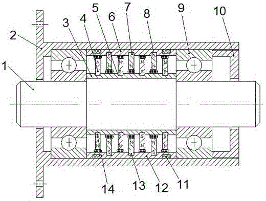
[0021] Such as figure 1 The split-type staggered magnetic fluid sealing device includes a shaft 1, a housing 2, an inner pole shoe ring 3, a split-type outer pole shoe, a split-type inner permanent magnet, and a split-type outer permanent magnet. The shaft 1 described above is installed in the housing, the inner wall cross sections of the shaft 1 and the housing 2 are mutually concentric circles, the inner pole shoe ring 3 is set on the shaft 1, and the outer surface of the inner pole shoe ring 3 A plurality of annular grooves I5 are provided at intervals;

[0022] The split-type outer pole shoe and the inner pole shoe ring 3 correspond to each other, and their axial lengths are equal, and the inner diameter of the split-type outer pole shoe is larger than the outer diameter of the inner pole shoe ring 3; the split-type outer pole shoe The pole piece includes an oute...


PUM


Abstract

The invention relates to the technical field of mechanical engineering sealing, in particular to a split alternating magnetofluid sealing device. The device comprises an inner pole shoe ring, a split outer pole shoe, split inner permanent magnets and a split outer permanent magnets, wherein the split outer pole shoe is positioned outside the inner pole shoe ring, and the inner diameter of the split outer pole shoe is more than the outer diameter of the inner pole shoe ring; a plurality of annular grooves I are alternately formed in the outer circumference of the inner pole shoe ring, and the split inner permanent magnets are arranged in the annular grooves; a plurality of annular grooves II are alternately formed in the inner circumference of the split outer pole shoe, and the split outer permanent magnets are arranged in the annular grooves II; the annular grooves I are positioned on the center line of every two annular grooves II, and the annular grooves II are positioned on the center line of every two annular grooves I; the split inner permanent magnets extend into the space among the split outer permanent magnets, and the split outer permanent magnets extend into the space among the split inner permanent magnets. The sealing device can be used for improving the pressure resistance of a split magnetofluid sealing device.

Description

technical field [0001] The invention relates to the technical field of mechanical engineering sealing, in particular to a split-type interlaced magnetic fluid sealing device with simple structure and reliable sealing performance. Background technique [0002] The magnetic fluid seal has the advantages of zero leakage, long life, high reliability, etc. It has been widely used in all walks of life, but the traditional magnetic fluid sealing device is an integral structure. In the process of assembling the sealing device, it is necessary to first Install the shaft end into the sealing device, and then connect the shaft end of the equipment with complex equipment. When the shaft end of the rotating shaft where the magnetic fluid seal is located is connected to complex equipment, inconvenient to assemble and disassemble or even not allowed to disassemble, not only the assembly process requires It takes a lot of time, the assembly effect is affected, and it is difficult to replace...

Claims


Application Information

Patent Timeline
Patent Type & Authority Applications(China)
IPC IPC(8): F16J15/43
CPCF16J15/43
Inventor 杨小龙
Owner GUANGXI UNIVERSITY OF TECHNOLOGY
Why Eureka
Try Eureka