LED lamp filament lamp with built-in power source and thermal radiation material

An LED filament lamp and LED filament technology, applied in the field of lighting, can solve the problems of cumbersome processes, difficult heat dissipation, limited space, etc., and achieve the effects of improving heat dissipation effect, improving production efficiency, and high production efficiency

Pending Publication Date: 2016-11-09
SHANDONG PROSPEROUS STAR OPTOELECTRONICS TECH CO LTD
View PDF4 Cites 10 Cited by
  • Summary
  • Abstract
  • Description
  • Claims
  • Application Information

AI Technical Summary

Problems solved by technology

This assembly method of installing the driver in the lamp holder has the following defects: (1) Since the lamp holder is a conductive metal, the driver must be put on an insulating sleeve before being put into the lamp holder, which requires manual operation, cumbersome procedures, and low efficiency. In addition, due to The space inside the lamp holder is narrow, and after putting in the driver, the bonding space between the lamp holder and the bulb shell is not enough, the bonding fastness is reduced, and it is easy to fall off, and the bonding needs to go through a high temperature of 300 degrees, which will affect the life of the electronic components in the driver. Large, high comprehensive failure rate
(2) Since the LED filament bulb lamp generally does not contain a radiator, the temperature of the LED filament is high during operation, and it is difficult to dissipate heat, which affects the life of the light source
In addition, the power supply is inside the lamp holder, the space is limited, the heat generated is not easy to dissipate to the outside, and the life of the power supply is also greatly affected

Method used


Image

  • LED lamp filament lamp with built-in power source and thermal radiation material
  • LED lamp filament lamp with built-in power source and thermal radiation material
  • LED lamp filament lamp with built-in power source and thermal radiation material

Examples


Embodiment Construction

[0022] The present invention will be further described below in conjunction with the accompanying drawings and specific embodiments, so that those skilled in the art can understand the present invention.

[0023] Such as figure 1 as shown,

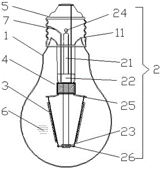
[0024] A power supply built-in LED filament lamp with heat radiation material, comprising a bulb shell 1, a stem 2 with a bracket 22, at least one LED filament 3, a driver 4 and a lamp cap 5, the bulb shell 1 and the stem 2 are vacuum Seal to form a vacuum-sealed cavity; a high thermal conductivity gas 6 is arranged in the vacuum-sealed cavity; the stem 2, LED filament 3 and driver 4 are all located inside the vacuum-sealed cavity; the bracket 22 is located at the end of the stem 2, and the driver 4 is fixed On the upper part of the support 22; the lower end of the support 22 is provided with a wire 26; the upper end of the support 22 is provided with an electrode lead-out line 25; one end of the LED filament 3 is connected in series with...


PUM


Abstract

The invention discloses an LED lamp filament lamp with a built-in power source and a thermal radiation material and relates to the technical field of lighting. The LED lamp filament lamp with the built-in power source and the thermal radiation material comprises a blister body, a core column with a support, at least one LED lamp filament, a driver and a lamp holder; the blister body and the core column are sealed in vacuum to form a vacuum sealed cavity; high-heat-conductivity gas is arranged in the vacuum sealed cavity; the core column, the LED lamp filament and the driver are all located in the vacuum sealed cavity; and the outer surface of the LED lamp filament and the outer surface of the driver are each provided with a thermal radiation material layer. The LED lamp filament lamp with the built-in power source and the thermal radiation material has the beneficial effects of being high in production efficiency, good in cooling effect, long in service life, low in cost and the like.

Description

technical field [0001] The invention relates to the technical field of lighting, in particular to a LED filament lamp with a built-in power supply and a heat radiation material. Background technique [0002] Based on the consideration of energy saving and environmental protection, incandescent lamps are gradually being abandoned by people. LED bulbs have the characteristics of long life, high luminous efficiency, no radiation and impact resistance, and are gradually replacing incandescent lamps. [0003] However, due to the directivity of the light emitted by the LED light source itself, even after the emitted light is diffused by the diffusion cover, compared with the traditional incandescent light source that can distribute light in all directions, the light distribution angle of the existing LED bulb lamp is still very large. Narrow, the light distribution angle is generally below 120°, the light cannot reach the back of the lamp, and shadows will be formed. Therefore, ...

Claims


Application Information

Patent Timeline
Patent Type & Authority Applications(China)
IPC IPC(8): F21K9/232F21K9/237F21K9/238F21V19/00F21V23/00F21V23/06F21V29/508H05B33/08F21Y113/10F21Y115/10H05B44/00H05B45/10H05B45/3725
CPCF21V19/001F21V23/003F21V23/06F21V29/508H05B45/00F21K9/232F21Y2107/00F21Y2115/10
Inventor 马文波廖秋荣孔一平袁信成周民康
Owner SHANDONG PROSPEROUS STAR OPTOELECTRONICS TECH CO LTD
Why Eureka
Try Eureka