
Premixing strong swirling flow flame diffusion burner

A technology of diffusion combustion and swirler, which is applied to burners, gas fuel burners, combustion methods, etc., can solve the problems of increasing premixed gas opening angle, increasing combustion range, and small combustion range, and achieves improved combustion. Effects of efficiency, increased heating area, wide fuel spreadability

Active Publication Date: 2016-11-09
BEIHANG UNIV
View PDF8 Cites 11 Cited by
  • Summary
  • Abstract
  • Description
  • Claims
  • Application Information

AI Technical Summary

Problems solved by technology

[0008] The technical problem to be solved by the present invention is to provide a swirl burner that can provide a larger heating range in view of the shortcomings of the existing swirl burner with a small combustion range and a small heating area. Taking advantage of the advantages of the pre-combustion stage for ignition and flame stability, the gaseous fuel and air are pre-mixed and passed through the cyclone, which can effectively improve the combustion efficiency and reduce air pollution; the main combustion stage structure of the central stage cyclone is designed as a strong cyclone The flow structure can effectively increase the opening angle of the premixed gas in the downstream diffusion and increase the combustion range, while the ignition effect of the pre-combustion stage flame on the main combustion stage premixed gas can effectively solve the ignition problem of the main combustion stage

Method used


Image

  • Premixing strong swirling flow flame diffusion burner
  • Premixing strong swirling flow flame diffusion burner
  • Premixing strong swirling flow flame diffusion burner

Examples


Embodiment Construction

[0029] The present invention will be described in detail below in conjunction with the accompanying drawings and specific embodiments.

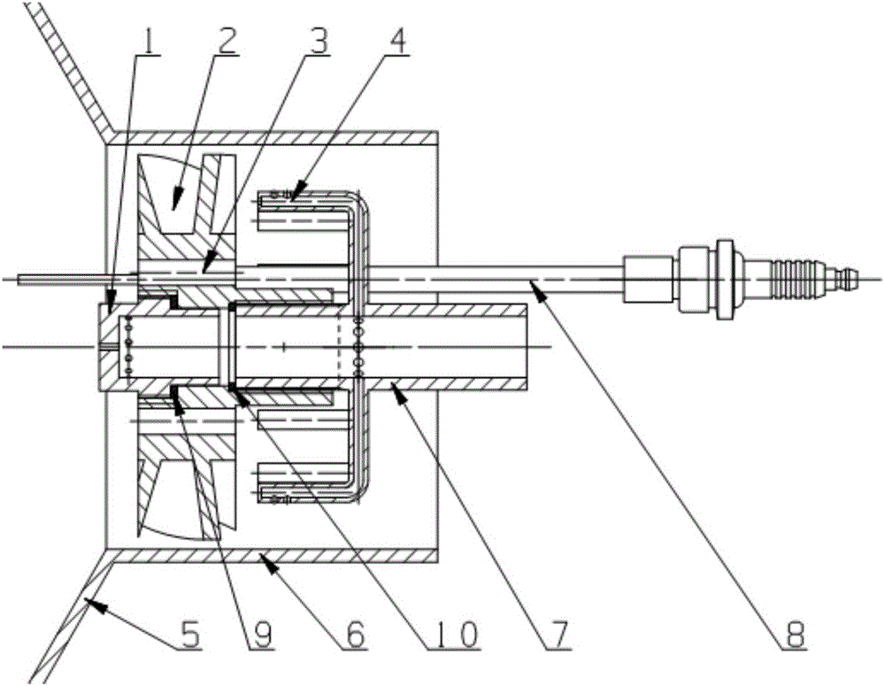
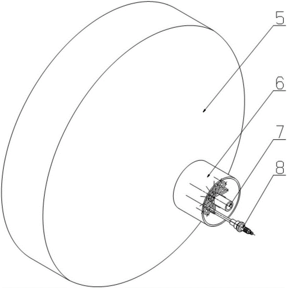
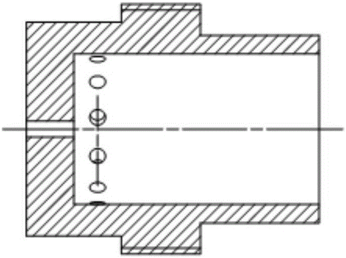
[0030] Such as figure 1As shown in this embodiment, a premixed strong swirling flame diffusion burner adopts a centrally graded design structure and is made of stainless steel as a whole. The burner part includes: a pre-combustion stage nozzle 1, a swirler 2, The pre-combustion stage air hole 3 and the main combustion stage nozzle 4, as well as the fuel pipeline 7 for supplying fuel, the air pipeline 6 for supplying air, the electric spark igniter 8 for starting the burner and the casing of the combustion chamber for the combustion reaction process 5. The gaseous fuel is fed into the device through the fuel pipeline 7, and a part of the fuel directly enters the combustion chamber through the pre-combustion stage nozzle 1 to carry out diffusion combustion with the pre-combustion stage air passing through the pre-combustion stage air hole 3; t...


PUM


Abstract

The invention discloses a premixing strong swirling flow flame diffusion burner. Center grading structure design is adopted. The premixing strong swirling flow flame diffusion burner comprises a combustion box, an air pipeline, a fuel pipeline, a swirler, a precombustion level air hole, a precombustion level nozzle and a main combustion level nozzle. The air pipeline is connected with an inlet of the combustion box through welding and is used for guiding air to pass through the swirling flow burner and enter a combustor for combustion. The fuel pipeline supplies gaseous fuel to the precombustion level nozzle and the main combustion level nozzle, wherein 25%-40% of the fuel enters the precombustion level nozzle and is then sprayed into the combustor to be mixed with precombustion level air directly entering the combustor through the precombustion level air hole for diffusive combustion. Through a premixing strong swirling flow flame diffusion structure adopted by the burner, the downstream combustion area can be enlarged well, the heating area is enlarged, thus a larger space range can be heated through the burner with a small area, meanwhile, the combustion efficiency is improved, and pollutant discharge is reduced.

Description

technical field [0001] The invention relates to a swirl burner, in particular to a premixed strong swirl flame diffusion burner. Background technique [0002] The combustion of coal, oil, and natural gas is the source of thermal power for various sectors of the national economy. Using the chemical reaction of combustion, various combustion devices that obtain heat from fuel are also widely used in various metal smelting, boilers, etc. In industrial and civil fields such as equipment and scientific research experiments, the structural design of the burner in the combustion device is the main factor to achieve a good combustion effect. It determines the ignition performance of the combustion device and the flame distribution and temperature distribution in the flow field. For the combustion device Safe operation and economic benefits play a very important role. [0003] At present, most of the combustion devices of boiler equipment and large-scale heat exchangers use the mech...

Claims


Application Information

Patent Timeline
Patent Type & Authority Applications(China)
IPC IPC(8): F23D14/04F23D14/64F23D14/70F23D14/58
CPCF23D14/04F23D14/58F23D14/64F23D14/70F23D2203/007F23D2900/14003F23D2900/14021
Inventor 王建臣陈启典张岩林宇震张弛
Owner BEIHANG UNIV
Learn More