A countercurrent induced draft feed dryer

A dryer and feed technology, which is applied in the direction of static material dryer, granular material drying, local mixing dryer, etc., can solve the problems of large-scale machinery not in line with economic benefits, farmers' unaffordable price, and small scale of feed use. Achieve the effect of reducing labor intensity, simple structure and good drying effect

Active Publication Date: 2018-07-20
山东成基饲料股份有限公司
View PDF6 Cites 0 Cited by
  • Summary
  • Abstract
  • Description
  • Claims
  • Application Information

AI Technical Summary

Problems solved by technology

[0002] Agricultural feed drying machines are usually large in size. In China’s family production, feed is used on a small scale. It is not economical to purchase large machines, and the price is unaffordable for farmers.

Method used


Image

  • A countercurrent induced draft feed dryer

Examples


Embodiment Construction

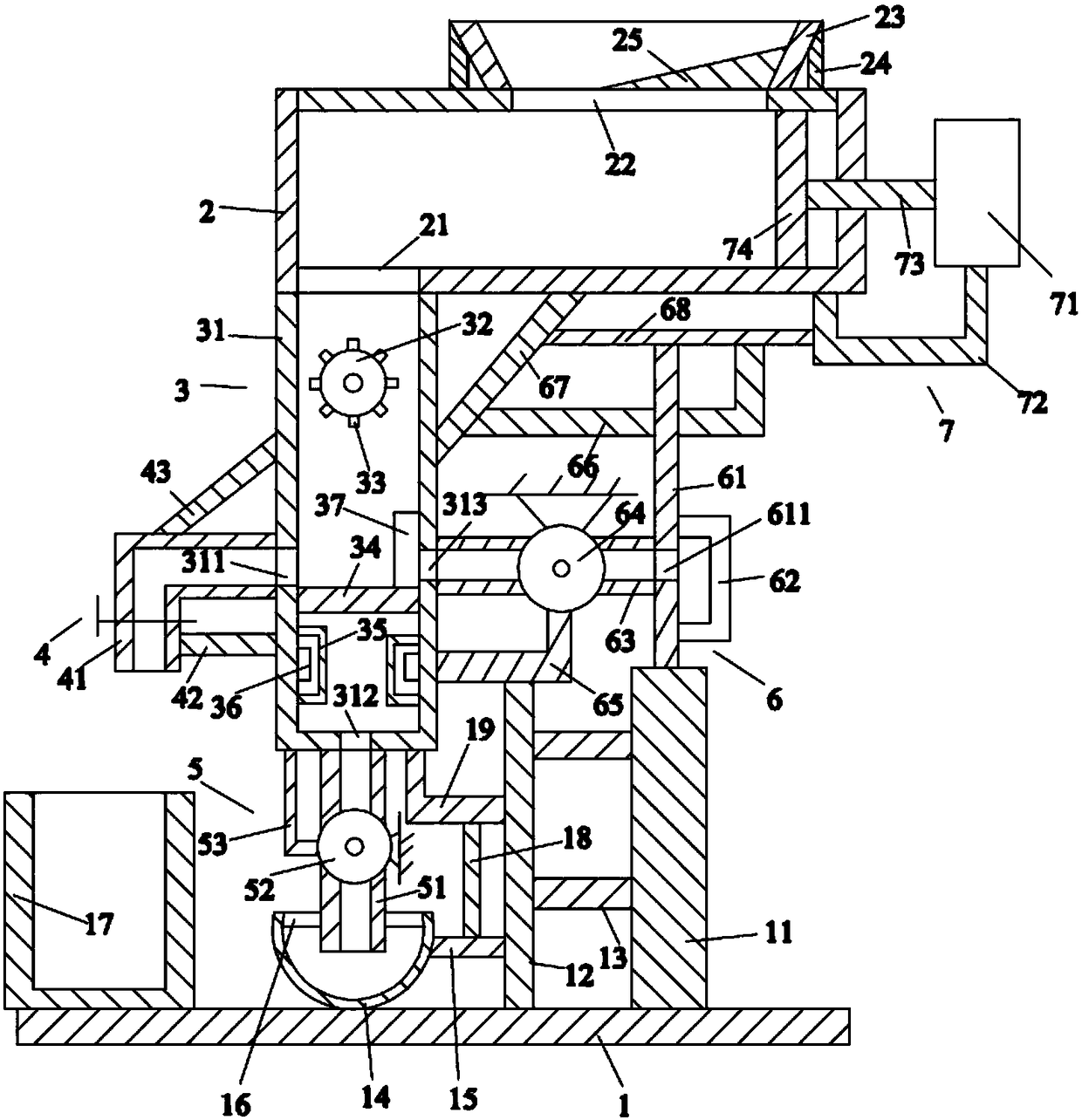
[0019] Such as figure 1 As shown, the countercurrent induced draft feed dryer of the present invention includes a base plate 1, a frame body 2 located above the base plate 1, a drying device 3 located below the frame body 2, and a discharge device located on the left side of the drying device 3 4. An air extraction device 5 located below the drying device 3 , an air blowing device 6 located on the right side of the drying device 3 , and a material pushing device 7 arranged on the frame body 2 .

[0020] Such as figure 1 As shown, the base plate 1 is a cuboid, and the base plate 1 is placed horizontally. The base plate 1 is provided with a first support rod 11 above it and a second support rod 12 on the left side of the first support rod 11. , the first cross bar 13 on the right side of the second support bar 12, the purification frame 14 on the left side of the second support bar 12, the second cross bar 15 on the right side of the purification frame 14, accommodated in The ...


PUM


Abstract

A backflow air-induced forage drier comprises a bottom plate, a frame body, a drying device, a discharging device, an air exhaust device, an air blowing device and a material pushing device. The bottom plate is provided with a first supporting rod, a second supporting rod, first transverse rods, a purification frame, a second transverse rod, a first filter screen, a recovery box, a first vertical rod and a first support. The frame body is provided with a first through hole, a second through hole, a feed hopper, second vertical rods and a material collection block. The drying device comprises a box body, an idler wheel, another first through hole, a second filter screen, heat dissipation frames, a heating rod and a third filter screen. The discharging device comprises a discharging pipe, a first valve, a third transverse rod and a first diagonal rod. The air exhaust device comprises an air exhaust pipe, a first fan and a second support. The air blowing device comprises an air blowing pipe, a second fan, a vertical plate, a fourth filter screen, a third support, a fourth transverse rod, a second diagonal rod and a fifth transverse rod. The material pushing device comprises an air cylinder, a fixing rack, a push rod and a push plate. The backflow air-induced forage drier can thoroughly dry forage, and is good in drying effect.

Description

technical field [0001] The invention relates to the technical field of agricultural machinery, in particular to a countercurrent induced draft feed dryer. Background technique [0002] Agricultural feed drying machines are usually large in size. In China's family production, the scale of feed use is small. It is not economical to purchase large machines, and the price is unaffordable for farmers. [0003] Therefore, it is necessary to provide a new technical solution to solve the above technical problems. Contents of the invention [0004] The object of the present invention is to provide a countercurrent induced draft feed dryer that can effectively solve the above technical problems. [0005] In order to solve the above technical problems, the present invention adopts the following technical solutions: [0006] A countercurrent induced draft feed dryer, the countercurrent induced draft feed dryer comprises a bottom plate, a frame above the bottom plate, a drying device...

Claims


Application Information

Patent Timeline
Patent Type & Authority Patents(China)
IPC IPC(8): F26B9/06F26B21/06F26B25/00
CPCF26B9/063F26B21/003F26B21/06F26B25/002F26B2200/08
Inventor 刘汉佑
Owner 山东成基饲料股份有限公司
Why Eureka
Try Eureka