Experimental device and method for measuring Young modulus through beam bending method on basis of resonance principle

A technology of Young's modulus and experimental equipment, applied in the field of university physics experiments, can solve problems affecting the accuracy of experimental results, many precautions, and affecting the accuracy of measurement results, etc.

Inactive Publication Date: 2016-11-09
田凯
View PDF1 Cites 0 Cited by
  • Summary
  • Abstract
  • Description
  • Claims
  • Application Information

AI Technical Summary

Problems solved by technology

[0005] First, the static tensile method is usually used to measure the Young's modulus of metal materials, and the principle is relatively simple
[0006] Second, according to the optical lever amplification principle, the sag of the midpoint of the rectangular cross-section metal beam is measured through the amplification system composed of the optical lever, the telescope and the ruler. Although the method is ingenious, the principle is abstract and difficult to understand, and the adjustment of the telescope is relatively difficult. It is large, and there are many precautions, and it is very easy to get tired and make mistakes in the data, which will affect the accuracy of the measurement results.
[0007] Third, weights are generally used to apply tension to metal beams, and the calculation of tension with the nominal mass of weights is inaccurate, thus affecting the accuracy of experimental results
[0008] Fourth, the plane mirror of the optical lever is generally made of glass, which is easily damaged during the experiment
[0009] Fifth, the scale illuminator generally adopts a small straight tube fluorescent lamp, the brightness is not easy to adjust, and it is easy to be damaged, and because there is a capacitor in the power supply device, if it is not discharged in time after use, the experimenter will be easily shocked by electric shock

Method used


Image

  • Experimental device and method for measuring Young modulus through beam bending method on basis of resonance principle
  • Experimental device and method for measuring Young modulus through beam bending method on basis of resonance principle
  • Experimental device and method for measuring Young modulus through beam bending method on basis of resonance principle

Examples


Embodiment Construction

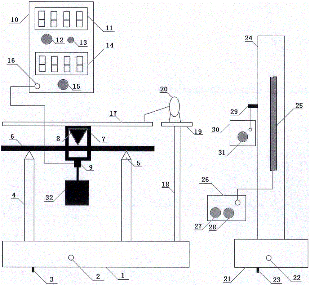
[0044] Among the figure, two columns 4 are set on the base 1, and a steel knife edge is respectively fixed at the upper ends of the two columns 4, i.e. the column knife edge 5, the blades of the two knife edges are parallel to each other, and the two ends of a rectangular cross-section metal beam 6 freely straddle the Placed on the edge of the upper ends of the two columns 4, a copper frame 7 is placed on the rectangular cross-section metal beam 6, and the contact between the copper frame 7 and the rectangular cross-section metal beam 6 is also a knife edge, that is, the copper frame knife edge 8, and the copper frame knife edge 8 Just in the middle of the knife edges at the upper ends of the two uprights, a vibrator 9 is set at the lower end of the copper frame 7 , the vibrator 9 is connected to the iron block 32 through a connecting device, and a platform 17 is set at the upper end of the copper frame 7 . The exciter 9 is connected to the sinusoidal signal source 10 through t...


PUM


Abstract

The invention provides an experimental device and method for measuring Young modulus through a beam bending method on the basis of a resonance principle, and relates to a Young modulus measuring device and method. The invention aims at solving the problems that an existing experiment principle for measuring the Young modulus through the beam bending method is single and abstract, and a telescope is difficult to adjust. According to the experimental device, two stand columns are arranged on a base, the two ends of a metal beam with a rectangular cross section are freely arranged on cutting edges at the upper ends of the stand columns in a crossing mode, the metal beam is sleeved with a copper frame, the lower end of the copper frame is provided with a vibration exciter and an iron block, the vibration exciter is connected with a signal source, and a laser is arranged on a scaleplate. According to the experimental method for measuring the Young modulus through the beam bending method on the basis of the resonance principle, a sinusoidal signal is converted into mechanical vibration by means of the vibration exciter, a metal beam spring oscillator is subjected to forced vibration, the vibration enables light spots formed on the scaleplate by reflecting a laser beam through a plane mirror of an optical lever to rotate by means of an amplification system composed of the laser and the optical lever, the signal frequency is adjusted, the inherent frequency of the metal beam spring oscillator is obtained when the vibration amplitude is the largest, and the Young modulus is calculated out. The experimental device and method for measuring the Young modulus through the beam bending method on the basis of the resonance principle are suitable for measuring the Young modulus.

Description

technical field [0001] The invention relates to a university physics experiment, in particular to an experimental device and method for measuring Young's modulus by a beam bending method based on the resonance principle. Background technique [0002] The change in shape of a solid under the action of an external force is called deformation. It can be divided into elastic deformation and normative deformation. The deformation that an object can completely return to its original shape after the external force is removed is called elastic deformation. If the external force applied to the object is too large, so that after the external force is removed, the object cannot completely return to its original shape, leaving residual deformation, which is called normative deformation. In this experiment, only elastic deformation is studied. Therefore, the magnitude of the external force should be controlled to ensure that the object can return to its original shape after the extern...

Claims


Application Information

Patent Timeline
Patent Type & Authority Applications(China)
IPC IPC(8): G01N3/34G01N3/06G09B23/10
CPCG01N3/34G01N3/068G01N2203/0005G01N2203/0023G01N2203/0039G01N2203/0075G01N2203/0098G01N2203/0264G09B23/10
Inventor 田凯张金平董雪峰王二萍张洋洋
Owner 田凯
Why Eureka
Try Eureka