Fault recording device based on voltage traveling wave principle and range finding method

A technology of fault recording device and voltage traveling wave, which is applied in the direction of fault location, measuring device, fault detection according to conductor type, etc. It can solve the problems that the traveling wave plug-in does not play a corresponding role, cannot meet the configuration requirements, and cannot be satisfied. To achieve the effect of speeding up the efficiency of line inspection, accurate discovery and ensuring high efficiency

Active Publication Date: 2016-11-09
WUHAN ZHONGYUAN HUADIAN SCI & TECH
View PDF11 Cites 16 Cited by
  • Summary
  • Abstract
  • Description
  • Claims
  • Application Information

AI Technical Summary

Problems solved by technology

[0005] CN201310059206 uses the current signal to analyze the traveling wave algorithm. The traveling wave plug-in can access 15 current signals at most, and for a common double-bus wiring substation, there are at least 64 current channels in the case of full configuration, so this disclosure The technology cannot meet the configuration requirements. When the faulty line is one of the (64-15) lines that are not configured with the traveling wave channel, the traveling wave plug-in does not play a corresponding role, which has great limitations.
[0006] CN201310059206 Traveling wave sampling rate is 1M, which can no longer meet the requirements of the current standard (the national standard requires that the sampling rate of traveling wave ranging is not less than 2M), and is limited by the performance of the hardware platform and the communication rate of the built-in switch (under the adoption rate of 2M, 15 channel current Wave data traffic is 480Mb, much larger than the switch traffic limit)

Method used


Image

  • Fault recording device based on voltage traveling wave principle and range finding method
  • Fault recording device based on voltage traveling wave principle and range finding method
  • Fault recording device based on voltage traveling wave principle and range finding method

Examples


Embodiment Construction

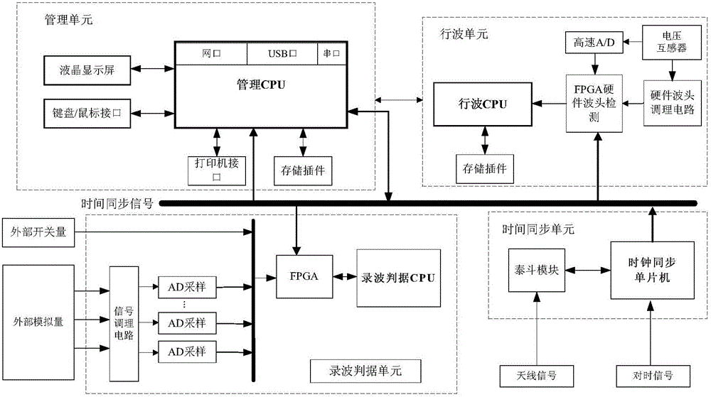
[0033] Such as figure 1 As shown, a fault recording device based on the voltage traveling wave principle of the present invention includes a recording criterion unit, a traveling wave unit, a time synchronization unit, and a management unit, and is characterized by: a recording criterion unit, a traveling wave unit , The time synchronization unit and the management unit are installed in the fault recorder. The management unit interacts with the traveling wave unit and the recorder criterion unit respectively. The recorder criterion unit is responsible for judging the start of the recorder and the calculation of various characteristic parameters. ; The traveling wave unit is responsible for determining the arrival time of the traveling wave wave head and the storage of the traveling wave waveform; the time synchronization unit is connected to the required time module to provide reliable and accurate system time for the device; the management unit is responsible for the communicati...


PUM


Abstract

The invention relates to a fault recording device based on a voltage traveling wave principle and a range finding method. The fault recording device based on a voltage traveling wave principle comprises a recording criterion unit, a traveling wave unit, a time synchronization unit, and a management unit which are all installed in a wave recorder simulating cabinet. The management unit is connected with the traveling wave unit and the recording criterion unit. The recording criterion unit determines recording activation and computes various characteristic parameters. The traveling wave unit determines the coming time of the head of a traveling wave in combination with software and hardware. The time synchronization unit is connected with a required time module and provides reliable and accurate system time for the device. The management unit performs communication management, recording management, comprehensive criterion management, and system task management. A bus voltage travelling wave is integrated into the fault recording device so as to increase power transmission line fault point positioning accuracy in the fault recording device and greatly shorten fault line inspection and fault repair time.

Description

Technical field [0001] The invention relates to the technical field of power system relay protection fault recording and distance measurement, in particular to a fault recording device and a distance measurement method based on the principle of voltage traveling waves. Background technique [0002] High-voltage transmission lines and transmission corridors are complex and prone to failure. In particular, UHV transmission lines have long transmission distances, are exposed to the wilderness, and are mostly mountainous and hilly terrain, which is the place with the highest failure rate in the high-voltage transmission grid. Transmission line failure poses a greater threat to the safe operation of the system, and also brings a heavy burden to line operation and maintenance personnel to find fault points. The fast and accurate location of the fault point can greatly shorten the time for fault repair, reduce the loss caused by power outage, and improve the reliability of system opera...

Claims


Application Information

Patent Timeline
Patent Type & Authority Applications(China)
IPC IPC(8): G01R31/08
CPCG01R31/085G01R31/088
Inventor 王永业张小波熊少华冯维纲黄勇郭海蛟李凡
Owner WUHAN ZHONGYUAN HUADIAN SCI & TECH
Why Eureka
Try Eureka