Control system applied to a variety of grids and working method thereof

A control system and grid technology, applied in general control system, control/regulation system, program control, etc., can solve the problems of low grid management and monitoring efficiency

Inactive Publication Date: 2016-11-09
江苏杜氏环保科技有限公司
View PDF7 Cites 0 Cited by
  • Summary
  • Abstract
  • Description
  • Claims
  • Application Information

AI Technical Summary

Problems solved by technology

[0008] Purpose of the invention: The purpose of the present invention is to provide a control system and its working method applied to various grids, to solve the problem of low efficiency of existing grid management and monitoring, to improve the efficiency of subsequent biochemical improvement, to realize real-time monitoring and Early warning requirements, improve the service life and work efficiency of the grille, reduce the workload of control and maintenance personnel, and prevent water pollution caused by sewage leakage

Method used


Image

  • Control system applied to a variety of grids and working method thereof
  • Control system applied to a variety of grids and working method thereof
  • Control system applied to a variety of grids and working method thereof

Examples


Embodiment 1

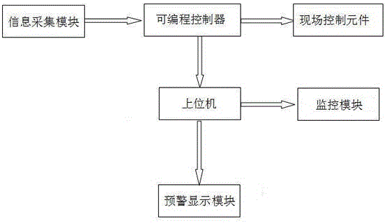
[0022] Such as Figure 1 to Figure 13 The control system applied to various grids shown is composed of a power circuit, an incoming switch connected to the power circuit, and a control component; the control component includes an information collection module and a programmable control module connected to the information collection module. system, and the field control elements, the upper computer connected with the programmable control system, and the monitoring module and the early warning display module respectively connected with the upper computer.

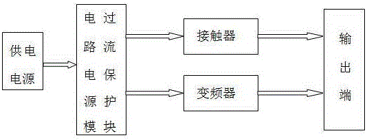
[0023] Further preferably, the control system also includes a load circuit connected to the control component; wherein, the load circuit includes a power supply, a circuit power overcurrent protection module connected to the power supply, and a circuit power overcurrent protection module connected to the power supply respectively. Connected contactors, frequency converters, and output terminals connected to contactors and fre...

Embodiment 2

[0029] Such as Figure 1 to Figure 13 The control system applied to various grids shown is composed of a power circuit, an incoming switch connected to the power circuit, and a control component; the control component includes an information collection module and a programmable control module connected to the information collection module. system, and the field control elements, the upper computer connected with the programmable control system, and the monitoring module and the early warning display module respectively connected with the upper computer.

[0030]Further preferably, the control system also includes a load circuit connected to the control component; wherein, the load circuit includes a power supply, a circuit power overcurrent protection module connected to the power supply, and a circuit power overcurrent protection module connected to the power supply respectively. Connected contactors, frequency converters, and output terminals connected to contactors and freq...


PUM


Abstract

The invention belongs to the technical field of sewage treatment equipment mechanical application, and specifically discloses a control system for a variety of grids. The control system is composed of a power circuit, and an incoming switch and a control assembly which are connected with the power circuit. The control assembly comprises an information acquisition module, a programmable control system connected with the information acquisition module, a field control component and a principal computer connected with the programmable control system, and a monitoring module and an early warning and display module connected with the principal computer. The control system applied to a variety of grids and a working method thereof disclosed by the invention have the following beneficial effects: firstly, the key transmissions and damageable parts of a grid are monitored, and the running time is accumulated; and secondly, when the service life of the transmissions and damageable parts of the grid reaches a preset schedule time for maintenance, maintenance personnel are reminded to conduct maintenance, the alarm is raised for contents needing maintenance, the last maintenance time is displayed to the maintenance personnel, and the current maintenance time is recorded automatically.

Description

technical field [0001] The invention belongs to the technical field of mechanical application of sewage treatment equipment, and in particular relates to a control system applied to various grids and a working method thereof, so as to realize real-time monitoring of the working state. Background technique [0002] Sewage treatment (sewage treatment, wastewater treatment) is the process of purifying sewage to meet the water quality requirements of a certain water body for drainage or reuse. Sewage treatment is widely used in construction, agriculture, transportation, energy, petrochemical, environmental protection, Various fields such as urban landscape, medical care, and catering are also increasingly entering the daily lives of ordinary people. [0003] The topic of water pollution is constantly being brought up, especially the problem of groundwater pollution. Farmers or entrepreneurs in Zhejiang Hangzhou, Wenzhou and other places have paid for the director of the Environm...

Claims


Application Information

Patent Timeline
Patent Type & Authority Applications(China)
IPC IPC(8): G05B19/05
CPCG05B19/058G05B2219/14006
Inventor 杜玉伟
Owner 江苏杜氏环保科技有限公司
Why Eureka
Try Eureka