Isolated type fireproof cable

A fireproof cable and isolation technology, applied in the field of wire and cable, can solve the problems of failing to achieve cooling and extinguishing the flame, insufficient flexibility of the stainless steel sleeve, and reduced explosion-proof performance of the cable, achieving good waterproof and explosion-proof effect, good waterproof and explosion-proof effect , The effect of preventing mechanical damage

Inactive Publication Date: 2016-11-09
CHONGQING CITY SOUTH FLAME RETARDANT WIRE & CABLE CO LTD
View PDF6 Cites 7 Cited by
  • Summary
  • Abstract
  • Description
  • Claims
  • Application Information

AI Technical Summary

Problems solved by technology

[0004] Disadvantages of Patent Document 1: 1. Stainless steel is used as the outermost protective sheath. The stainless steel sheath is easily damaged by external stress, resulting in a decrease in the explosion-proof performance of the cable, and the flexibility of the stainless steel sheath is not enough; 2. The

Method used


Image

  • Isolated type fireproof cable

Examples


Embodiment 1

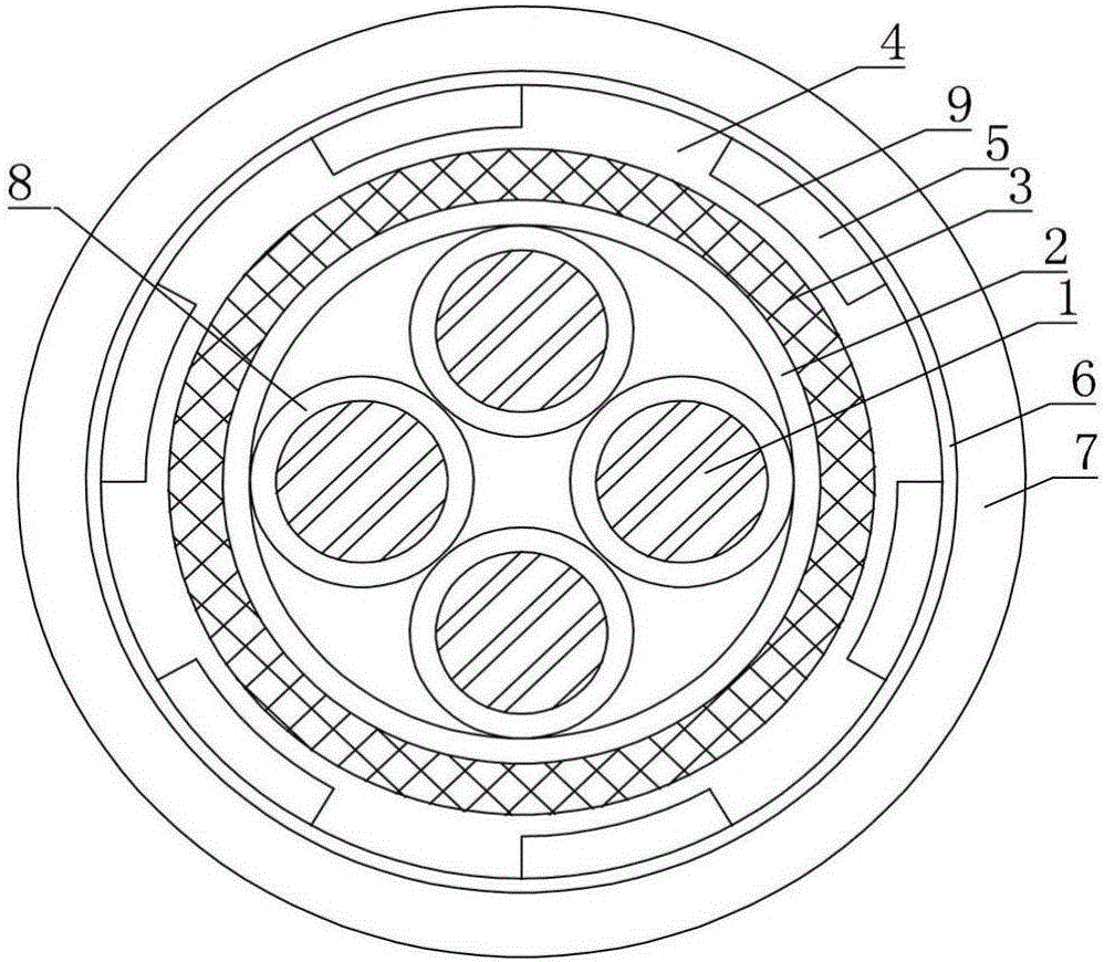
[0038] Such as figure 1 As shown, an isolated fireproof cable includes a conductor 1, an outer insulating layer 2 located outside the conductor 1, an insulating sleeve 3 located outside the outer insulating layer 2, a toothed sleeve 4 located outside the insulating sleeve 3, and a toothed sleeve 4 located outside the outer insulating layer 2. The fireproof layer 5 on the outer side of the shape sleeve 4, the halogen-free flame-retardant tape 6 outside the fireproof layer 5, the low-smoke halogen-free sheath 7 outside the halogen-free flame-retardant tape 6;

[0039] The conductor 1 is formed by twisting wires, and each wire is provided with an inner insulating layer 8, and the inner insulating layer 8 is composed of a mineral compound;

[0040] The outer insulating layer 2 consists of a mineral compound;

[0041] The isolation sleeve 3 is a metal sleeve;

[0042] The toothed sleeve 4 is a cross-linked polyethylene toothed sleeve, and accommodating grooves 9 are formed betwee...

Embodiment 2

[0048] Such as figure 1 As shown, an isolated fireproof cable includes a conductor 1, an outer insulating layer 2 located outside the conductor 1, an insulating sleeve 3 located outside the outer insulating layer 2, a toothed sleeve 4 located outside the insulating sleeve 3, and a toothed sleeve 4 located outside the outer insulating layer 2. The fireproof layer 5 on the outer side of the shape sleeve 4, the halogen-free flame-retardant tape 6 outside the fireproof layer 5, the low-smoke halogen-free sheath 7 outside the halogen-free flame-retardant tape 6;

[0049] The conductor 1 is formed by twisting wires, and each wire is provided with an inner insulating layer 8, and the inner insulating layer 8 is composed of a mineral compound;

[0050] The outer insulating layer 2 consists of a mineral compound;

[0051] The isolation sleeve 3 is a metal sleeve;

[0052] The toothed sleeve 4 is a cross-linked polyethylene toothed sleeve, and accommodating grooves 9 are formed betwee...


PUM

PropertyMeasurementUnit
Thicknessaaaaaaaaaa

Abstract

The invention discloses an isolated type fireproof cable, belongs to the wire and cable field, and solves the problems that the laying effect of a fireproof layer is bad and the explosion-proof effect is bad for the existing cable. The isolated type fireproof cable comprises a conductor, an outer insulating layer at an outer side of the conductor, an isolated sleeve tube arranged at an outer side of the outer insulating layer, a tooth form sleeve arranged out of the isolated sleeve tube, a fireproof layer arranged at an outer side of the tooth form sleeve, a halogen-free flame retardant band arranged at an outer side of the fireproof layer, and a low-smoke halogen-free sheath arranged out of the halogen-free flame retardant band. The conductor is formed by twisting conductive wires. An inner insulating layer is arranged out of each conductive wire and formed by a mineral compound. The outer insulating layer is formed by a mineral compound. The isolated sleeve tube is a metal sleeve tube. The fireproof layer is laid more evenly through the tooth form sleeve, and the explosion-proof performance of the cable is improved. The machinery damage of the conductor is avoided by arranging the isolated sleeve tube. The fireproof layer can cool and dilute the flame during the combustion and quench the flame.

Description

technical field [0001] The invention belongs to the field of wires and cables, in particular to an isolated fireproof cable. Background technique [0002] Patent Document 1 A reinforced isolation mineral insulated flexible fireproof cable (application number: 201610030335.7; publication number: 105551603A) includes a core, a fireproof layer, a tape layer and an outer sheath. The wire cores are twisted into a cable core, the outside of the cable core is wrapped with a tape layer, and the outer sheath is wrapped around the outside of the tape layer. The gap between the wire cores, the gap between the wire core and the tape layer is filled with a fireproof layer. The wire core is composed of a conductor, an insulation layer, a reinforcement layer, an isolation layer and an oxygen barrier layer. The insulation layer is wrapped around the outside of the conductor, the reinforcement layer is wrapped around the outside of the insulation layer, and the isolation layer is extruded o...

Claims


Application Information

Patent Timeline
IPC IPC(8): H01B7/295H01B7/18H01B7/282H01B7/02
CPCY02A30/14H01B7/295H01B7/0216H01B7/18H01B7/282
Inventor 王红梅
Owner CHONGQING CITY SOUTH FLAME RETARDANT WIRE & CABLE CO LTD
Why Eureka
Try Eureka