Insulating piercing wire clamp and dedicated installation tool therefor

A technology of insulation puncture and wire clamp, which is applied in the direction of needle point/slotted plate contact pieces used for penetrating insulated wires/cable core wires, contact members with insulating cutting edges, electrical components, etc., which can solve the problem of small current carrying capacity, Problems such as damage to the metal conductor, small contact section between the insulation piercing clamp and the metal conductor, etc.

Inactive Publication Date: 2016-11-09
国网江西省电力有限公司九江供电分公司 +2
View PDF7 Cites 7 Cited by
  • Summary
  • Abstract
  • Description
  • Claims
  • Application Information

AI Technical Summary

Problems solved by technology

[0004] (1) The clamping force of the entire cable insulation piercing clamp to the main cable and the branch cable is provided and maintained by a bolt. In order to achieve the best results of the aforementioned two technical requirements at the same time, it is necessary to rely on excellent structural design and precision. The size control of the existing cable insulation piercing clamp is difficult, the process requirements are very high, and the price is expensive. This balanced state is difficult to achieve and is not conducive to maintenance.
[0005] (2) During use, the cable insulation piercing clamp and the cable will inevitably experience different degrees of thermal expansion and contraction under the action of temperature difference, and there is no stress compensation mechanism between the cable insulation piercing clamp and the cable, which will make the joint Looseness, that is, the contact between the piercing blade and the metal conductor is poor, and the insulation layer and the sealing rubber pad are not tightly matched, so that the cable insulation piercing clamp cannot work stably for a long time; at the same time, the increase in the contact resistance between the piercing blade and the metal conductor will make the contact part The temperature is too high, which further shortens the working life of the cable insulation

Method used


Image

  • Insulating piercing wire clamp and dedicated installation tool therefor
  • Insulating piercing wire clamp and dedicated installation tool therefor
  • Insulating piercing wire clamp and dedicated installation tool therefor

Examples


Embodiment Construction

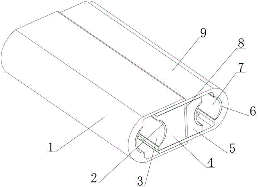
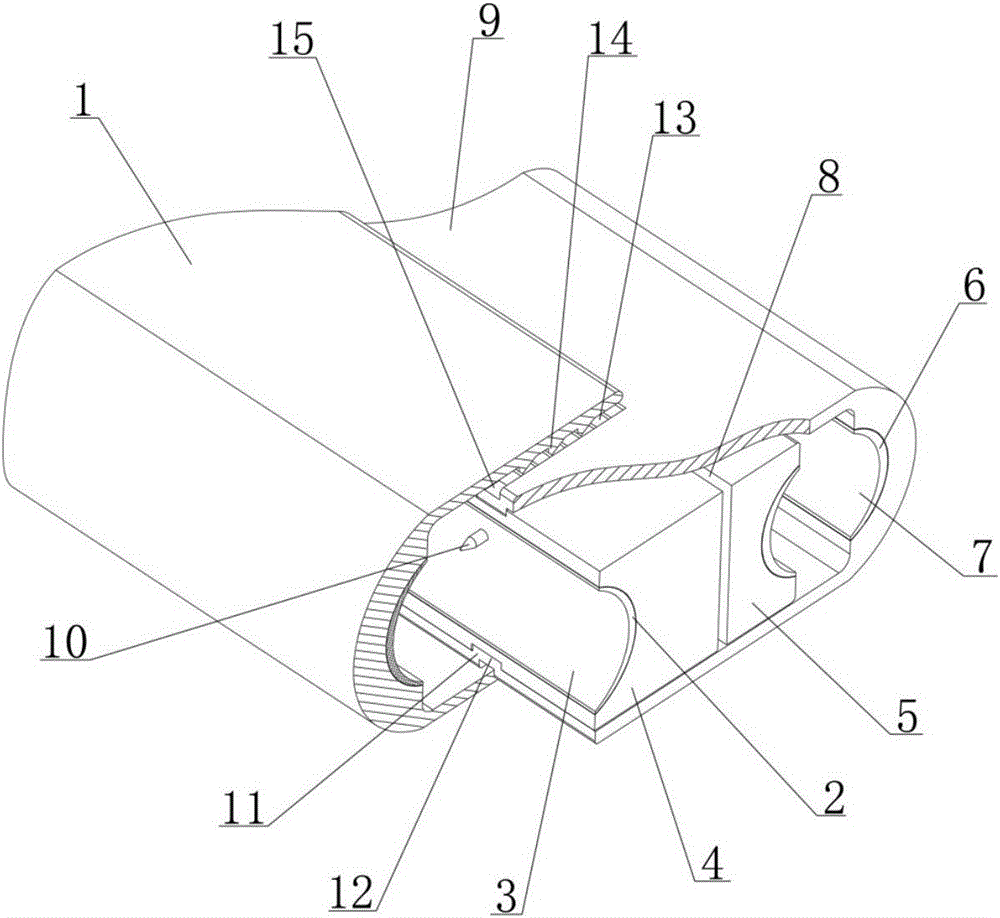
[0058] see figure 1 , 2 As shown, an insulation piercing clamp disclosed by the present invention is mainly composed of two parts: a wire clamp assembly and a wire clamp shell assembly;

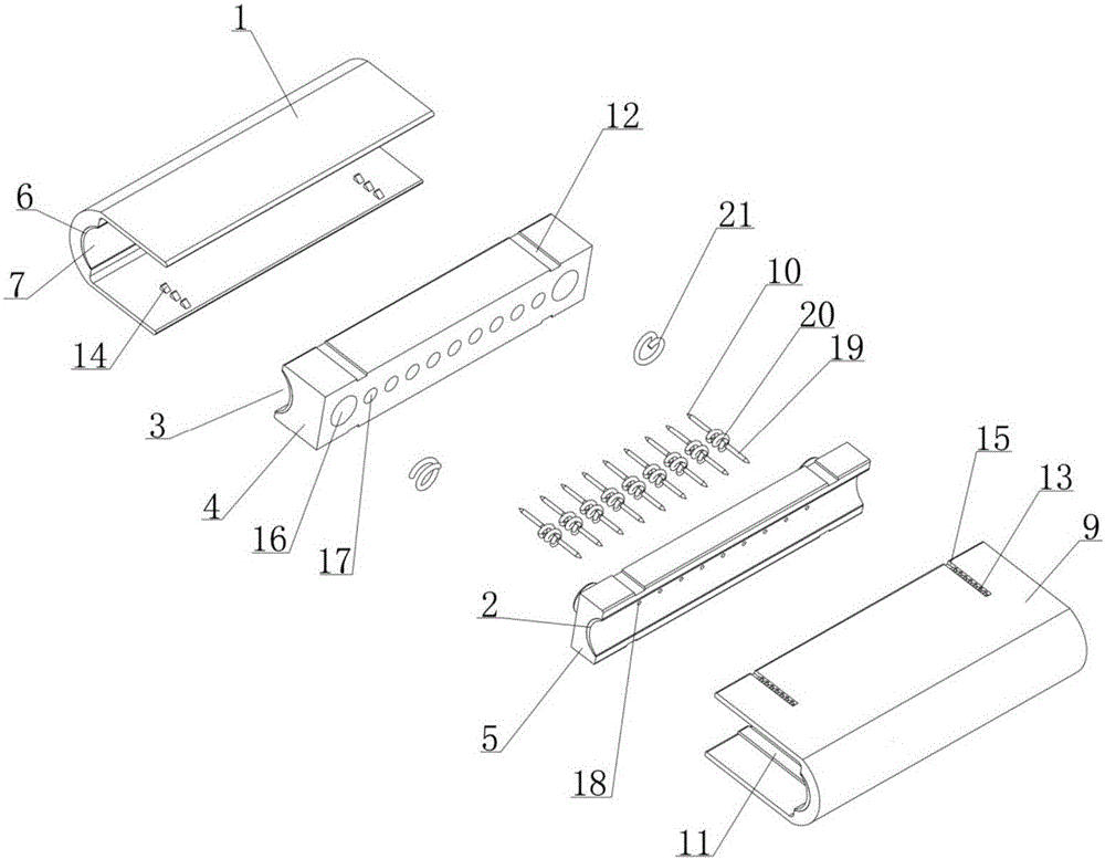
[0059] Among them, see Figure 1-5As shown, the wire sandwich assembly is in the shape of a cuboid as a whole, and its left and right side walls are respectively provided with a cable groove 3, and the two cable grooves 3 are parallel to each other, and the groove walls are respectively lined with sealing rubber pads 2; The sandwich assembly is composed of a left core block 4 and a right core block 5 with a buffer gap 8, and a transverse guide mechanism A and a thrust spring 21 are arranged between the left core block 4 and the right core block 5 to make the wire sandwich assembly in the width direction It can be elastically stretched, and the size of the buffer gap 8 changes accordingly when the wire sandwich assembly elastically expands; there are N parallel guide wire holes 18 in the wir...


PUM


Abstract

The invention discloses an insulating piercing wire clamp, and the wire clamp consists of a wire clamp core assembly and a wire clamp case assembly. The wire clamp core assembly can stretch out and draw back laterally, and the left and right side walls of the wire clamp core assembly are respectively provided with a cable duct. The interior of the wire clamp core assembly is provided with N wire holes and N wire seats. There are N metal wires, and the spiral telescoping parts of the metal wires are respectively disposed in the wire seats. Two piercing pointed ends at two sides of each spiral telescoping part respectively stretch into two cable ducts. The wire clamp case assembly comprises a left case and a right case, and the inner sides of the bottoms of the left and right cases are respectively provided with a wire pressing groove. The left case is clamped outside the right case, and there is a guide non-return mechanism between the left and right cases. Two groups of opposite wire pressing grooves and the cable ducts enable a main cable and branch cables to be clamped firmly, and each metal wire enable the main cable to be connected with the branch cables. After the insulating piercing wire clamp is installed, the insulating piercing wire clamp is good in sealing performance, is low in contact resistance, is high in stability, and can carry out the buffering of deformation and strain changes caused by temperature difference. Therefore, the insulating piercing wire clamp is long in service life, is stable in operation, is low in cost, and is convenient to install.

Description

technical field [0001] The invention relates to a cable connection accessory, in particular to an insulation piercing clamp for cable branch connection and a special installation tool thereof. Background technique [0002] The cable insulation puncture clamp is a cable branch connection device introduced and developed in recent years. It is mainly composed of an insulating shell, a puncture blade, a waterproof rubber pad, and a torque bolt. When making a cable branch connection, the branch cable is inserted into the branch line. After confirming the position of the branch of the main line, use a socket wrench to tighten the torque nut on the clamp. With the tightening of the torque nut, the two insulators with piercing blades hidden on the top and bottom of the clamp gradually close together, and the piercing blade penetrates the cable insulation layer and In contact with the metal conductor, at the same time, the arc-shaped sealing rubber pad wrapped around the piercing bla...

Claims


Application Information

Patent Timeline
IPC IPC(8): H01R11/01H01R11/09H01R4/24H01R43/01
CPCH01R4/2404H01R11/01H01R11/09H01R43/01
Inventor 王才丰
Owner 国网江西省电力有限公司九江供电分公司
Why Eureka
Try Eureka