
A wire junction box and an electronic detonator network with the junction box

A junction box and wire technology, which is applied in the direction of circuits, conductive connections, connections, etc., can solve the problems of electronic detonator identification information, low reliability and stability of card wire terminal connections, and low degree of automation in reading, etc., to achieve fast Accurate electrical connection, convenient and quick circuit detection, and the effect of controlling product yield

Active Publication Date: 2018-09-14
北京凯米迈克科技有限公司
View PDF8 Cites 0 Cited by
  • Summary
  • Abstract
  • Description
  • Claims
  • Application Information

AI Technical Summary

Problems solved by technology

[0006] In view of the above-mentioned defects, the technical problem to be solved by the present invention is to provide an optimized junction box to solve the problem of low connection reliability and stability of clamp terminals existing in the current technology, as well as the generation, marking and reading of electronic detonator identification information. The problem of low automation

Method used


Image

  • A wire junction box and an electronic detonator network with the junction box
  • A wire junction box and an electronic detonator network with the junction box
  • A wire junction box and an electronic detonator network with the junction box

Examples


Embodiment Construction

[0039] The following will clearly and completely describe the technical solutions in the embodiments of the present invention with reference to the accompanying drawings in the embodiments of the present invention. Obviously, the described embodiments are only some, not all, embodiments of the present invention. Based on the embodiments of the present invention, all other embodiments obtained by persons of ordinary skill in the art without making creative efforts belong to the protection scope of the present invention.

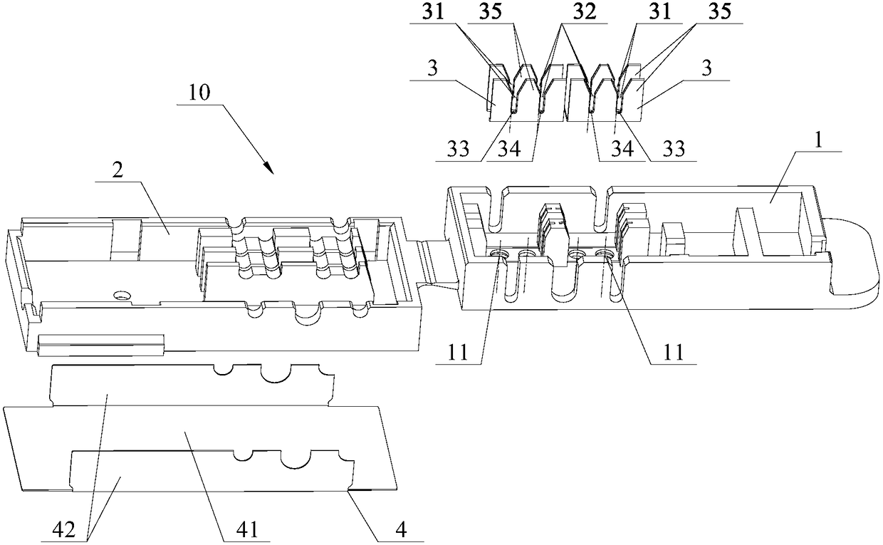
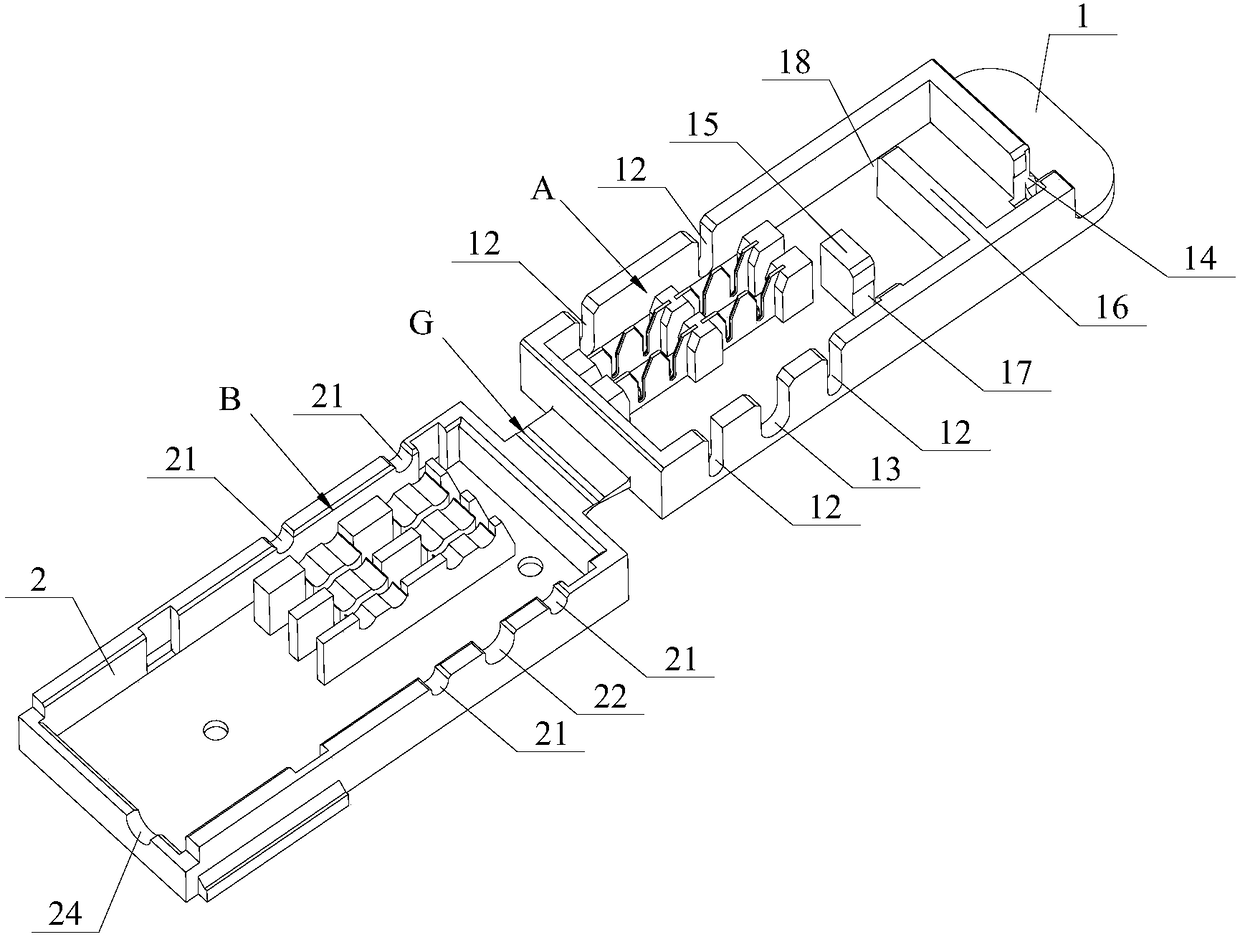
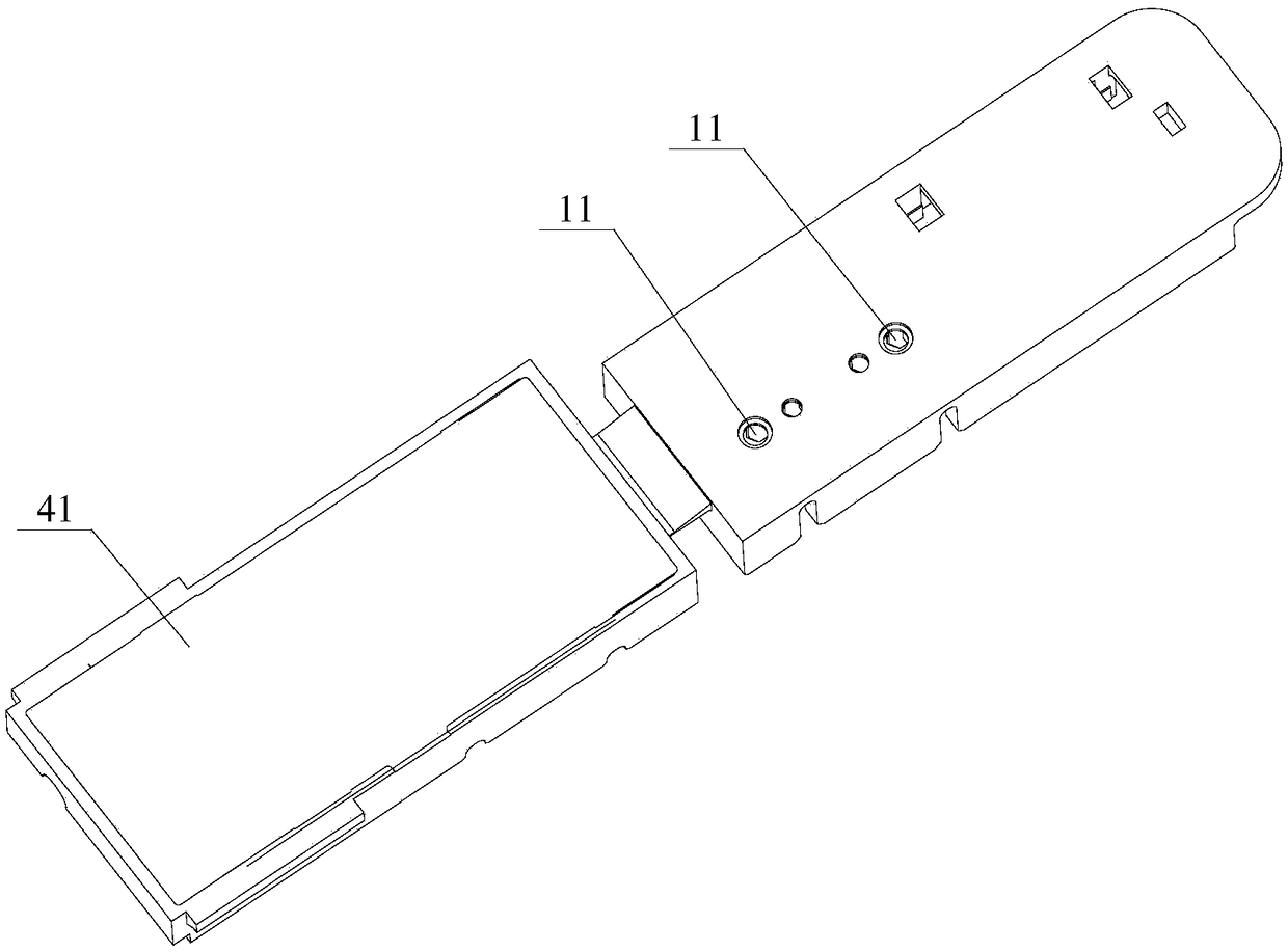
[0040] The core of this embodiment is to provide a junction box that can quickly realize wire connection, please refer to figure 1 , which is an exploded view of the assembly relationship of the wire junction box described in this embodiment. The wire junction box mainly includes: a foldable and snap-fit ​​junction box 10 body and a clamping terminal 3 placed in the base 1 of the body; Electrical connections are formed in the card slots (the bus bar card slot...


PUM


Abstract

The invention provides a lead conjunction box. The lead conjunction box includes a conjunction box main body which can be folded and buckled and a wire clamping terminal. The lead conjunction box main body has an upper cover which can press a lead to a groove of the wire clamping terminal so as to constitute electric connection. The lead conjunction box also includes a metal housing which is fixed to an external surface of the upper cover of the lead conjunction box main body, and the metal housing is easy to automatically etch identification information. The wire clamping terminal, the metal identification housing and the lead conjunction box main body adopt embedded injection molding into one body. Compared with prior art, the wire clamping terminal and a molded pedestal can be reliably connected therebetween so as to guarantee accurate relative position relationship between a groove on the wire clamping terminal and the main body structure, so that the cutting of lead sheath and reliable electric connection can be achieved in a rapid and accurate manner and the conjunction box can be repetitively used. Also, the conjunction box can maintain the identification information for a long time, is firm and reliable, guarantees transmission of electric signals and reliable execution so as to provide effective safeguard for safe and reliable execution of blasting network. The invention also provides an electronic detonator network having the same conjunction box.

Description

technical field [0001] The invention relates to the technical field of circuit connection accessories, in particular to a wire junction box in the field of civil blasting equipment and an electronic detonator network with the junction box. Background technique [0002] In actual application, the electronic detonator can control the detonation process through the electronic control module. As we all know, the accuracy, reliability and stability of the connection between the foot wire of the electronic detonator and the output bus of the initiator are the key indicators affecting the reliability of the electronic detonator network. [0003] In order to realize the reliable connection between the electronic detonator leg wire and the detonating bus bar, the prior art provides different forms of junction boxes, such as: "a junction box" disclosed in the Chinese patent literature with the publication number CN203504092U, and the "junction box" with the publication number CN203218...

Claims


Application Information

Patent Timeline
Patent Type & Authority Patents(China)
IPC IPC(8): H01R11/01H01R11/09H01R4/2433F42C19/12
CPCF42C19/12H01R4/2433H01R11/01H01R11/09
Inventor 张同来向江玉刘庆宇柳勤银庆宇
Owner 北京凯米迈克科技有限公司
Learn More