A Switching Device Driving Circuit Based on Charge Retention

A technology of switching devices and driving circuits, which is applied in the direction of electrical components, high-efficiency power electronic conversion, and climate sustainability. Poor performance and other problems, to achieve a wide range of applications, reduce the effective value, reduce the effect of core loss

Active Publication Date: 2019-04-02
FUZHOU UNIV
View PDF5 Cites 0 Cited by
  • Summary
  • Abstract
  • Description
  • Claims
  • Application Information

AI Technical Summary

Problems solved by technology

[0007] The disadvantages of this circuit are: when the power switch is fully turned on or off, its gate-source voltage floats to the ground and is not clamped to the power supply voltage or has a zero potential with low impedance, so the circuit has poor anti-interference performance and may be turned on by mistake or turn off
The single-tube resonant gate drive circuit can only drive one power MOSFET tube; the circuit has poor anti-interference and may be turned on or off by mistake
Dual power tube resonant gate drive circuit requires many devices and complex structure

Method used


Image

  • A Switching Device Driving Circuit Based on Charge Retention
  • A Switching Device Driving Circuit Based on Charge Retention
  • A Switching Device Driving Circuit Based on Charge Retention

Examples


Embodiment Construction

[0038] The technical solution of the present invention will be specifically described below in conjunction with the accompanying drawings.

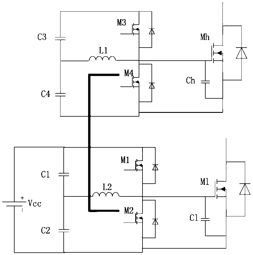
[0039] The present invention provides a low-loss drive circuit based on charge retention, such as Figure 4 As shown, it includes a transformer primary H bridge and a secondary secondary drive circuit; the transformer primary H bridge includes a first MOS switch M1, a second MOS switch M2, a third MOS switch M3 and a fourth MOS switch tube M4; the source of the first MOS switch tube M1 is connected to the drain of the second MOS switch tube M2, and connected to the same-named end of the primary winding of a transformer T; the source of the third MOS switch tube M3 is connected to the fourth MOS switch tube M2 The drain of the switch tube M4 is connected to the opposite end of the primary winding of the transformer T; the drain of the first MOS switch tube M1 is connected to the drain of the third MOS switch tube M3; the source of the seco...


PUM


Abstract

The invention relates to a switching device drive circuit based on charge retention, which includes a transformer primary side H bridge and a secondary side drive circuit; the H bridge includes a first MOS switch tube, a second MOS switch tube, and a third MOS switch tube and the fourth MOS switch; the secondary drive circuit on the secondary side includes a fifth MOS switch, a sixth MOS switch and a switch. The switching device drive circuit based on charge retention can effectively reduce the drive loss, improve the efficiency of the power electronic power converter, and overcome the large drive loss and poor anti-interference ability of the drive circuit of the existing power semiconductor device in the prior art. Deficiency of high class.

Description

technical field [0001] The invention relates to a driving circuit for driving power semiconductor devices, in particular to a switching device driving circuit based on charge retention. Background technique [0002] With the development of power electronics technology, the operating frequency of power semiconductor devices is getting higher and higher, and the driving loss of power semiconductors has become a non-negligible part. Reducing the driving loss of power semiconductors in power electronic power converters can effectively improve the efficiency and power density of power electronic power converters. [0003] The introduction and analysis of the existing MOSFET drive resonant drive circuit are as follows: [0004] 1 Single tube resonant gate drive circuit [0005] figure 1 Shown is a commonly used single-tube resonant gate drive circuit. The advantages of this circuit are: S1 and S2 can realize soft turn-on and zero-current turn-off; during the switching cycle, t...

Claims


Application Information

Patent Timeline
Patent Type & Authority Patents(China)
IPC IPC(8): H02M1/08
CPCH02M1/08H02M1/0058Y02B70/10
Inventor 陈庆彬刘坤荣陈为林苏斌
Owner FUZHOU UNIV
Why Eureka
Try Eureka