Insulation transformer and power conversion device using same

A technology for power conversion devices and insulating transformers, which is applied in the field of power conversion devices and insulating transformers. It can solve the problems of increasing winding resistance and winding loss, limiting the miniaturization of insulating transformers, and not mentioning the difference in the number of turns. Loss reduction, miniaturization, and temperature rise suppression effects

Pending Publication Date: 2022-01-04
MITSUBISHI ELECTRIC CORP
View PDF1 Cites 1 Cited by
  • Summary
  • Abstract
  • Description
  • Claims
  • Application Information

AI Technical Summary

Problems solved by technology

When miniaturizing an insulating transformer, it is necessary to increase the switching frequency, but as the switching frequency increases, the resistance value of the winding and the winding loss increase, so the miniaturization of the insulating transformer is limited
[0007] For example, in Patent Document 1, a thin high-current transformer is disclosed that reduces the high-frequency resistance of the windings by alternately stacking multiple layers of high-voltage side windings and low-voltage side windings, but does not mention the fact that the number of turns of each winding layer is different. situation, and does not show what structure is best in this case

Method used


Image

  • Insulation transformer and power conversion device using same
  • Insulation transformer and power conversion device using same
  • Insulation transformer and power conversion device using same

Examples


Embodiment approach 1

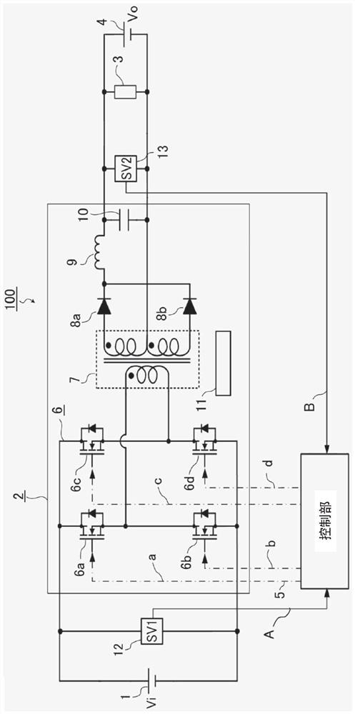
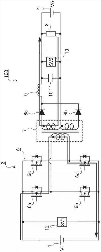
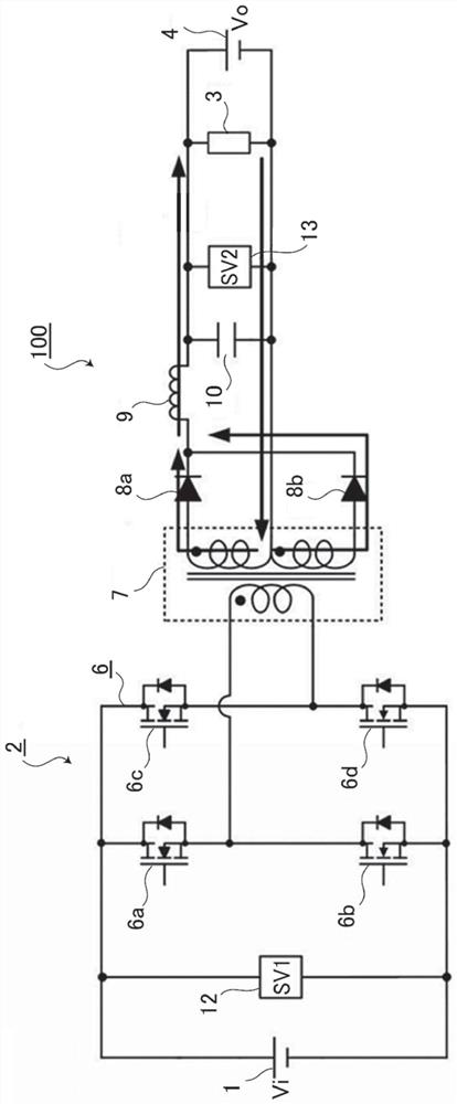
[0034] The power conversion device of Embodiment 1 includes a DC-DC converter for reducing the voltage of the high-voltage battery and supplying it to a load, a control unit, and a cooler. The DC-DC converter includes a power conversion section composed of semiconductor switching elements, an insulating transformer including a magnetic core forming a magnetic circuit, and a winding composed of a primary winding serving as a high-voltage winding and a secondary winding serving as a low-voltage winding, an insulating transformer, and a rectifier diode. department. The primary winding and the secondary winding of the insulating transformer respectively have a primary winding layer and a secondary winding layer formed by winding in the plane direction, and the winding portion is formed by alternately stacking the primary winding layer and the secondary winding layer, and the one with the largest number of turns The winding layers are arranged in layers other than the outermost lay...


PUM


Abstract

The invention provides an insulation transformer which can reduce winding loss of the insulation transformer, improve efficiency, restrain temperature rise of the winding and reduce size. The insulation transformer (7) has two types of windings, i.e., a high-voltage side winding (52) and a low-voltage side winding (53), the high-voltage side winding (52) and the low-voltage side winding (53) are formed by winding layers, the high-voltage side winding (52) comprises a winding formed by a plurality of winding layers (52a, 52b, 52c), among the windings formed by the plurality of winding layers (52a, 52b, 52c), one or more types of windings have winding layers with different numbers of turns, the winding layers in which a current flows in the same direction are stacked so as not to be adjacent to each other, and at least one layer (52b) of the winding layers (52b, 53c) having the largest number of turns is disposed in a layer other than the outermost layer.

Description

technical field [0001] The present application relates to an insulation transformer and a power conversion device using the same. Background technique [0002] Between power systems, power sources, etc., insulating power conversion devices capable of achieving electrical isolation between input and output are widely used. For example, the in-vehicle power supply system of a hybrid vehicle uses a dual-battery vehicle power supply device, and the output of the high-voltage battery supplies power to a low-voltage load through a step-down DC-DC converter. For such a power conversion device, miniaturization is always required in order to improve the loadability of an automobile. [0003] In order to realize the electrical isolation and voltage conversion between the input power supply and the load, the isolation type power conversion device adopts an isolation transformer. The insulating transformer is composed of a transformer core mainly composed of iron, and primary windings...

Claims


Application Information

Patent Timeline
Patent Type & Authority Applications(China)
IPC IPC(8): H01F27/28H02M3/335
CPCH01F27/28H02M3/3353H01F27/2876H02M3/33573H01F27/24H01F27/02
Inventor 田边隼翔
Owner MITSUBISHI ELECTRIC CORP
Why Eureka
Try Eureka