Flyback light emitting diode (LED) switching voltage stabilization driving power supply based on power factor correction circuit

A technology for power factor correction and driving power supply, applied in the field of electronics, can solve the problems of low power factor, low efficiency, low current control accuracy, etc., and achieve the effects of improving power factor, reducing power consumption, and high driving efficiency

Inactive Publication Date: 2016-11-09
CHENGDU JUHUICAI TECH
View PDF0 Cites 1 Cited by
  • Summary
  • Abstract
  • Description
  • Claims
  • Application Information

AI Technical Summary

Problems solved by technology

[0004] The purpose of the present invention is to overcome the defects of low efficiency, low power factor, and low current control accuracy in the LED switch drive power supply circuit in the prior art, and provide a flyback LED switch voltage regulator based on a power factor correction circuit drive power

Method used


Image

  • Flyback light emitting diode (LED) switching voltage stabilization driving power supply based on power factor correction circuit
  • Flyback light emitting diode (LED) switching voltage stabilization driving power supply based on power factor correction circuit
  • Flyback light emitting diode (LED) switching voltage stabilization driving power supply based on power factor correction circuit

Examples


Embodiment

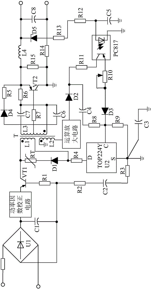
[0022] Such as figure 1 As shown, the present invention mainly consists of a control chip U2, a diode rectifier U1, a transformer T, a triode VT1, a resistor R1, a resistor R2, a resistor R3, a resistor R4, a thermistor RT, a polar capacitor C1, a polar capacitor C2, and a diode D1 , A power factor correction circuit, an operational amplifier circuit, a first-stage flyback circuit, and a constant current drive circuit.

[0023] During implementation, the anode of the polarity capacitor C1 is connected to the negative output terminal of the diode rectifier U1, and its negative terminal is connected to the positive output terminal of the diode rectifier U1. One end of the resistor R1 is connected to the base of the triode VT1, and the other end is connected to the negative electrode of the polarity capacitor C1. The anode of the polarity capacitor C2 is connected to the anode output terminal of the diode rectifier U1 through the resistor R2, and its cathode is connected to the ...


PUM


Abstract

The invention discloses a flyback light emitting diode (LED) switching voltage stabilization driving power supply based on a power factor correction circuit. The flyback LED switching voltage stabilization driving power supply is characterized by mainly comprising a control chip U2, a diode rectifier U1, an operational amplifier, a transformer T, a triode VT1, a diode D1, a primary flyback circuit, the power factor correction circuit and a constant current driving circuit, wherein the power factor correction circuit is connected in series between a negative electrode output end of the diode rectifier U1 and an emitter of the triode VT1, and the constant current driving circuit is connected with the transformer T and the primary flyback circuit separately. By the flyback LED switching voltage stabilization driving power supply, a current peak can be controlled to be constant, meanwhile, the switching duty ratio is controlled, the time proportion of the whole switching period is maintained and output constantly, so that constant output current is achieved; and moreover, the flyback LED switching voltage stabilization driving power supply only requires 0.5-microampere starting current, the starting power consumption is reduced, the efficiency of the flyback LED switching voltage stabilization driving power supply is greater than 80%, the no-load power consumption is smaller than 30mW, and thus, the efficiency of the flyback LED switching voltage stabilization driving power supply is improved.

Description

technical field [0001] The invention relates to the field of electronics, in particular to a flyback LED switching stabilized voltage driving power supply based on a power factor correction circuit. Background technique [0002] Under the background of global energy shortage and increasing environmental protection requirements, countries all over the world are vigorously developing green energy-saving lighting. As a revolutionary energy-saving lighting technology, LED lighting is developing rapidly. At the same time, people's requirements for LED switching drive power are also increasing. However, the existing LED switch driving power circuit has defects of low efficiency, low power factor, low current control accuracy, and low reliability, so the existing LED light switch driving power circuit cannot meet people's requirements. [0003] Therefore, it is urgent to provide an LED switching regulated driving power supply that can improve efficiency and power factor and ensure...

Claims


Application Information

Patent Timeline
IPC IPC(8): H05B33/08H05B44/00
CPCH05B45/00
Inventor 李考
Owner CHENGDU JUHUICAI TECH
Why Eureka
Try Eureka