Cryostation system

A storage system, low temperature technology, used in cryostats, heat insulation devices, household refrigeration devices, etc., can solve problems such as internal structure changes

Active Publication Date: 2016-11-09
HITACHI HIGH-TECH CORP
View PDF16 Cites 4 Cited by
  • Summary
  • Abstract
  • Description
  • Claims
  • Application Information

AI Technical Summary

Problems solved by technology

[0003] However, when water occupies most of it, such as biological samples, the volume shrinks due to

Method used


Image

  • Cryostation system
  • Cryostation system
  • Cryostation system

Examples


Embodiment 1

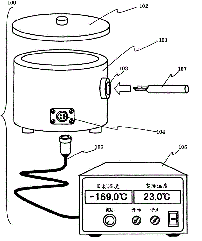
[0035] figure 1 A schematic configuration diagram of a cooling sample storage and transfer system according to an embodiment of the present invention is shown in . Hereinafter, the storage and transfer system of the cooled sample may be referred to as a "low temperature storage system".

[0036] The cryogenic storage system 100 is composed of a cryogenic storage main body 101 , a cover 102 , and a temperature adjustment unit 105 . Storage of the cooled sample and transfer to the sample rack can be performed inside the cryogenic storage main body unit 101 .

[0037] An insertion port 103 into which a sample holder 107 holding a sample can be inserted and a connection portion 104 connected to a cable 106 of a temperature adjustment unit 105 are provided in the cryogenic storage main body 101 . The temperature adjustment unit 105 includes a display unit that displays the actual internal temperature of the low-temperature storage main body 101 and the target cooling temperature ...

Embodiment 2

[0059] In Example 1, a case will be described in which the sample 113 is transferred to the sample holder 107 through the opening of the lid 102 using tools such as tweezers 114 .

[0060] In the present embodiment, a structure in which the sample 113 is more easily transferred to the sample holder 107 using the sample transfer mechanism 115 provided on the cryogenic storage main body 101 will be described.

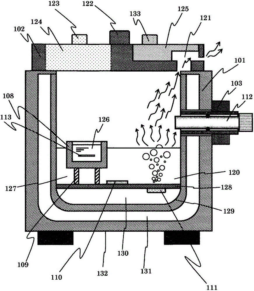
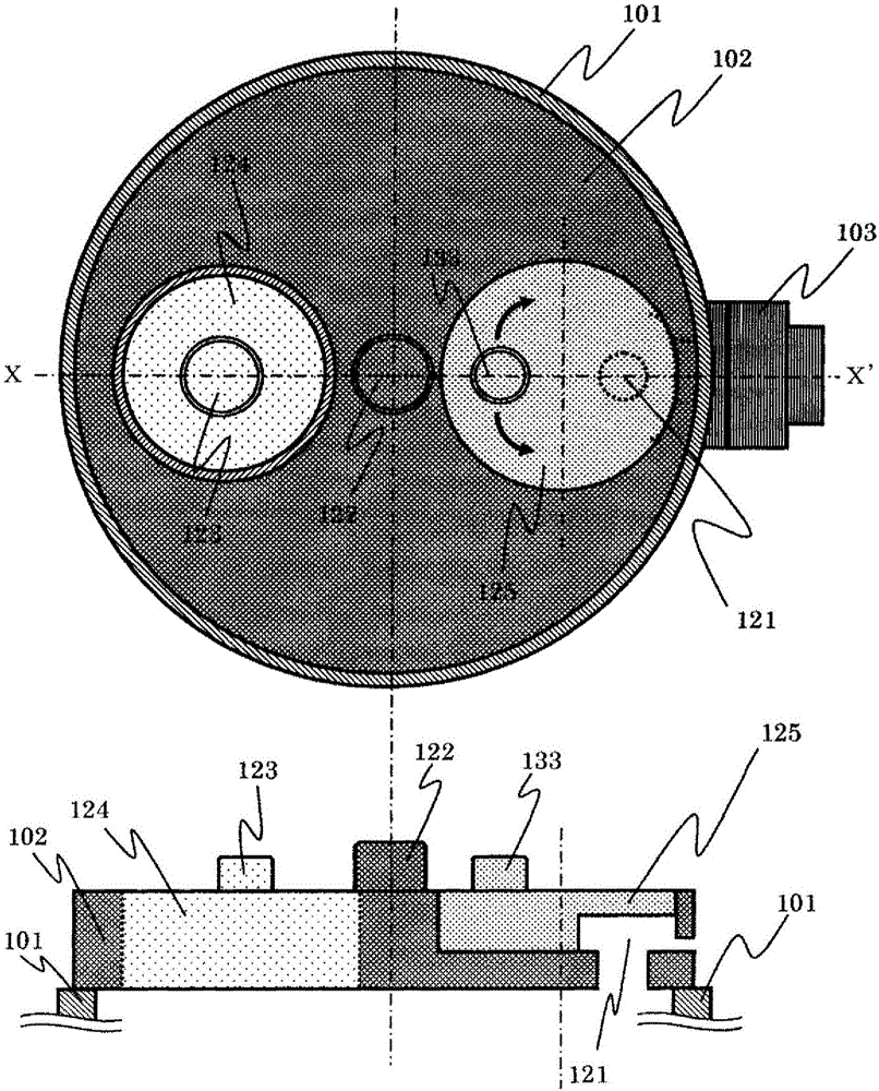
[0061] Figure 7 It is a schematic diagram showing the state at the time of sample transportation according to the present embodiment. Here, the low-temperature storage main unit 101 includes a sample transport mechanism 115 for more easily mounting a sample 113 cooled and stored in the sample storage unit 108 on the sample rack 107 .

[0062] The sample transfer mechanism 115 penetrates through the through hole provided in the cover part 102 and is provided inside the cryogenic storage body part 101 . The portion exposed to the outside from the cover portion 102 functi...

Embodiment 3

[0073] In this embodiment, a structure for more effectively preventing dew condensation and frost-like substances in the sample holder 107 will be described.

[0074] Figure 11It is a figure which shows the state when the sample 113 concerning this embodiment moves. Inside the insertion port 103 of the cryogenic storage body 101 , a sample rack heating unit 116 that transfers heat to the sample rack 107 is provided. According to this configuration, when the first cooling medium 120 vaporizes and rises toward the exhaust port 121 , condensation on the sample holder 107 is prevented.


PUM


Abstract

The present invention relates to a cooled sample subjected to freezing treatment, or the like, preventing the formation of condensation and frost-like substances and loads the sample into a sample holder for observation using a charged particle beam device. A cryostation system of the present invention is provided with a main body for storing a sample and a lid unit mounted above the main body. The main body is divided into a first space and a second space by a partition member. The first space accommodates a cooling medium for cooling the sample. The second space has, disposed therein, a heating unit for heating the cooling medium accommodated in the first space. The lid unit has, formed therein, a discharge port for discharging the gas generated by the heating of the cooling medium to the outside.

Description

technical field [0001] The present invention relates to the handling of samples for observation by charged particle beam devices such as electron microscopes, and particularly relates to techniques for storing and moving samples by cooling them without condensation or frost. Background technique [0002] In recent years, charged particle beam devices such as electron microscopes have been used for observation and analysis of samples having a fine structure. Generally, in these devices, the sample chamber in which the sample is placed is evacuated to make the sample environment a vacuum state. [0003] However, when moisture occupies most of it, such as a biological sample, the volume shrinks due to the evaporation of the moisture in the sample in a vacuum state, and a large change in the internal structure may occur. Regarding such a structure, as one of the treatments for observing a fine structure as close as possible to the original state, there is a method of instantane...

Claims


Application Information

Patent Timeline
IPC IPC(8): G01N1/28F25D3/10G01N1/00H01J37/20
CPCF25D3/102G01N1/42B01L7/04B01L7/50B01L2300/185H01J2237/2002H01J2237/204H01J2237/2001F25D3/10G01N1/28H01J37/20B01L2200/0684F25D3/105F25D21/04H01J2237/20214H01J2237/20235
Inventor 长久保康平岩堀敏行
Owner HITACHI HIGH-TECH CORP
Why Eureka
Try Eureka