
Voltage regulation in resonant power wireless receiver

A wireless receiving and receiving circuit technology, applied in the output power conversion device, the AC power input is converted into the DC power output, the current collector and other directions, which can solve the problems of efficiency loss and so on.

Inactive Publication Date: 2016-11-09
LINEAR TECH CORP
View PDF7 Cites 3 Cited by
  • Summary
  • Abstract
  • Description
  • Claims
  • Application Information

AI Technical Summary

Problems solved by technology

Since the incorporation of electronic varistors makes little sense, Q reduction is the practical solution, however the Q reduction caused by the additional resistors necessarily means additional power consumption and the ensuing loss of efficiency can quickly become a problem

Method used


Image

  • Voltage regulation in resonant power wireless receiver
  • Voltage regulation in resonant power wireless receiver
  • Voltage regulation in resonant power wireless receiver

Examples


Embodiment Construction

[0030] The present disclosure will be understood using specific examples presented below. However, the concepts of the present disclosure are applicable to various other modifications of the technologies discussed below.

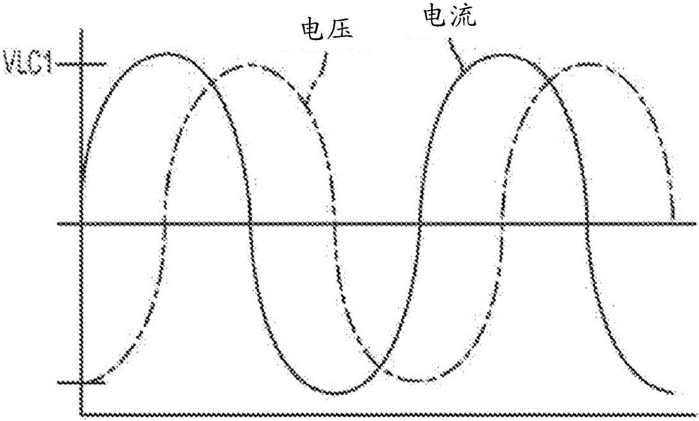
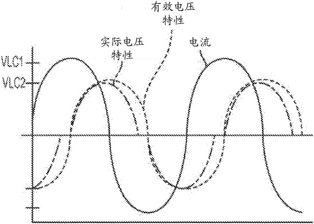
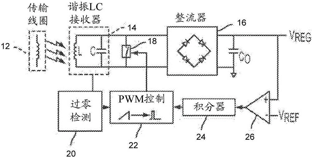
[0031] The disclosed technique uses a controllable shunt device to interrupt the voltage characteristic of the resonant capacitor for a controllable time during each cycle of resonant oscillation. For a given inductor current initial condition, the interruption of the capacitor's voltage response on a cycle-by-cycle basis reduces the peak circuit voltage for that given initial condition. By introducing a break in this cycle-by-cycle voltage characteristic, the overall response to the induced current is reduced, effectively simulating the increase in capacitance in a resonant circuit. Accordingly, the efficient receiver resonance is offset from the system transmit / receive frequency, reducing the voltage gain of the resonant LC receiver at that frequency. Th...


PUM


Abstract

A control system is provided for controlling a power receiving circuit which is configured for receiving power wirelessly and producing an output voltage. The power receiving circuit has a resonant LC circuit including an inductive element and a capacitive element coupled in parallel. The control system includes a switching circuit coupled in parallel to the resonant LC circuit, and a feedback loop circuit configured for regulating the output voltage by controlling duration during which the switching circuit is in a conductive state in each cycle of a voltage developed across the resonant LC circuit.

Description

[0001] related application [0002] This application claims priority to US Provisional Application No. 61 / 980,891, entitled "Voltage Regulation in Resonant Power Wireless Receivers," filed April 17, 2014, which is incorporated herein by reference. technical field [0003] The present disclosure relates to wireless power transfer, and more particularly to systems and methods for providing voltage regulation for resonant wireless power receivers. Background technique [0004] The field of wireless power transfer at low and medium power levels is currently focused on resonant technologies. A frequency control circuit is used to generate an alternating current (AC) current through a magnetic coil at a specific frequency, which acts as an energy transmitter. The magnetic flux established in the transmit coil excites the magnetic elements in the receiver circuit by electromagnetic induction. The receiver is based on a tuned LC circuit that resonates at a specific transmission fr...

Claims


Application Information

Patent Timeline
Patent Type & Authority Applications(China)
IPC IPC(8): H02J50/10H02J7/00H04B5/02H04B5/48
CPCH02J50/12H02M7/217Y02B70/10H02M1/0058
Inventor 乔纳森·韦德·切拉尼
Owner LINEAR TECH CORP
Learn More