
Novel separator feeder

A separator and feeder technology, applied in the direction of solid separation, etc., can solve the problems of polluting the working environment, sewage splashing, splashing outside the trough, etc.

Inactive Publication Date: 2016-11-16
芜湖恒固混凝土材料有限公司
View PDF5 Cites 0 Cited by
  • Summary
  • Abstract
  • Description
  • Claims
  • Application Information

AI Technical Summary

Problems solved by technology

[0004] However, the existing sand and gravel separation equipment has certain defects: when the water flow impacts the sand and gravel down, flows down from the mixing bucket of the concrete truck and enters the material tank, because the mixing tank has a certain height from the material tank , and the water flow is usually relatively fast, so that when the water flow enters the trough, it will have a large impact force on the wall and bottom of the trough, and under the action of this impact force, the water flow will have a strong impact due to collision. splash, so that the water splashes out of the trough, which not only cannot completely recover the sand and gravel in the water flow, causing losses, but also makes the sewage splash and pollute the working environment

Method used


Image

  • Novel separator feeder

Examples


Embodiment Construction

[0028] Specific embodiments of the present invention will be described in detail below in conjunction with the accompanying drawings. It should be understood that the specific embodiments described here are only used to illustrate and explain the present invention, and are not intended to limit the present invention.

[0029] In the present invention, unless stated otherwise, the orientation words such as "upward" included in the term only represent the orientation of the term in the normal use state, or the common name understood by those skilled in the art, and should not deemed to be a limitation of this term.

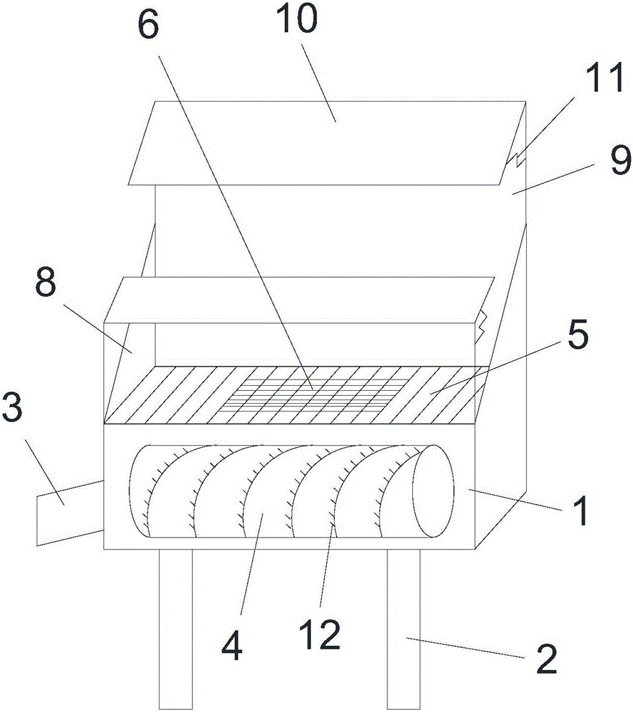
[0030] see figure 1 , the present invention provides a novel separator feeder, comprising a hopper 1, a support foot 2 and a discharge pipe 3;

[0031] One end of the discharge pipe 3 is connected with the hopper 1, and the other end extends toward the outside of the hopper 1, and the supporting foot 2 is installed at the bottom of the hopper 1;

[0032] The insi...


PUM

PropertyMeasurementUnit
Diameteraaaaaaaaaa
Diameteraaaaaaaaaa

Abstract

The invention discloses a novel feeder for a separator. One end of a discharge pipe is connected with a hopper, and the other end extends outward. The feeding pipe is extended; the driving mechanism drives the feeding screw to rotate; the top opening of the hopper is covered with a filter screen, and a grate is arranged in the middle of the filter screen. The mesh of the grate is smaller than the mesh of the filter screen; A pair of splash-proof components is provided, including a support plate and a splash-proof plate arranged vertically, the bottom end of the support plate is fixedly connected to the opening, one end of the splash-proof plate is hinged to the top of the support plate, and the other end is connected to the inner wall of the support plate through a spring; A pair of splash-proof components are connected through two side plates. The helical blades of the feeding screw are provided with multiple sets of metal brushes along the circumference, one end of the bristles is fixedly connected to the helical blades, and the other end extends outward. The structure is simple and the operation is convenient, which makes it difficult for sand and gravel to splash out and improves the separation efficiency of sand and gravel.

Description

technical field [0001] The present invention relates to concrete processing equipment and, in particular, to a novel separator feeder. Background technique [0002] Concrete is a general term for engineering composite materials in which aggregates are cemented into a whole by cementitious materials. Generally speaking, concrete refers to the cement concrete obtained by using cement as the cementitious material, sand and gravel as the aggregate, and mixing with water (additives and admixtures may be included) in a certain proportion, which is widely used in civil engineering. project. [0003] Sand and gravel separator, also known as concrete sand and gravel separator or concrete sand and gravel separation slurry water recovery equipment, is the core equipment of the concrete recovery system. [0004] However, the existing sand and gravel separation equipment has certain defects: when the water flow impacts the sand and gravel down, flows down from the mixing bucket of the ...

Claims


Application Information

Patent Timeline
IPC IPC(8): B03B11/00
CPCB03B11/00B03B2011/002
Inventor 承忠富
Owner 芜湖恒固混凝土材料有限公司
Learn More