
Flight attitude adjustment and control system for oil-drive multi-rotor agricultural plant protection helicopter

A technology of flight attitude and control system, applied in the field of aircraft, can solve the problems of troublesome maintenance, high requirements for technicians, high maintenance cost, etc., and achieve the effect of no maintenance cost, simple control system, and small load impact

Inactive Publication Date: 2016-11-16
ANYANG QUANFENG AVIATION PLANT PROTECTION TECH
View PDF9 Cites 5 Cited by
  • Summary
  • Abstract
  • Description
  • Claims
  • Application Information

AI Technical Summary

Problems solved by technology

[0002] Oil-powered multi-rotor helicopters have developed rapidly in recent years. Due to their long flight time and stable control, they have been widely used. When current oil-powered multi-rotor helicopters take off, the multi-rotors rotate simultaneously to generate downward airflow through the airflow. At the same time, the rotation direction of the two adjacent rotors is opposite, so that the rotation force of the helicopter in the circumferential direction of the fuselage cancels each other, so as to ensure that the fuselage does not rotate. When the helicopter needs to adjust the flight attitude, such as moving forward , back, turn and other actions, through the pitch adjustment mechanism, the pitch adjustment mechanism changes the rotor at the required azimuth inclination to generate the force required for the adjustment of the flight attitude. In the current oil-powered helicopter, this The complexity of the pitch adjustment mechanism has brought many disadvantages. First, the high precision required for manufacturing and the complicated assembly process increase the cost of the helicopter; The maintenance cost is high; the third is that this mechanism has high requirements on the flight control system, which is not conducive to reducing the cost of the aircraft

Method used


Image

  • Flight attitude adjustment and control system for oil-drive multi-rotor agricultural plant protection helicopter
  • Flight attitude adjustment and control system for oil-drive multi-rotor agricultural plant protection helicopter
  • Flight attitude adjustment and control system for oil-drive multi-rotor agricultural plant protection helicopter

Examples


Embodiment Construction

[0009] In order to more fully explain the implementation of the present invention, the implementation examples of the present invention are provided, and these implementation examples are only illustrations of the present invention, and do not limit the scope of the present invention.

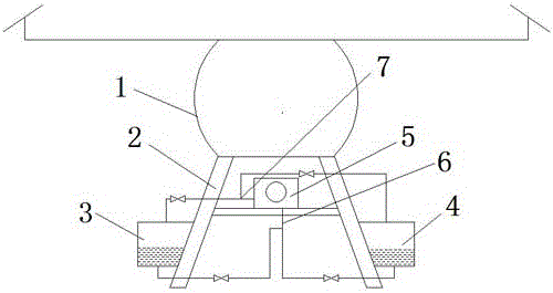
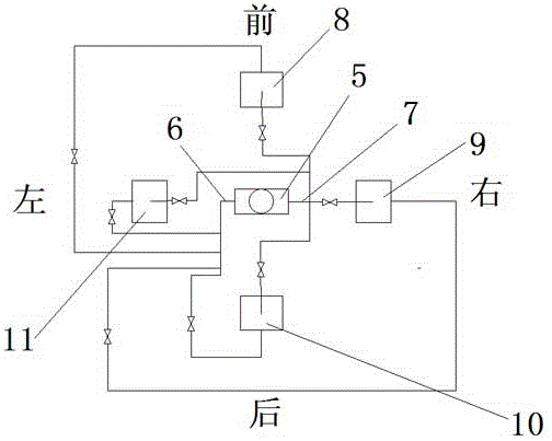
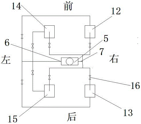
[0010] In conjunction with the accompanying drawings, the present invention is further described in detail. In the accompanying drawings, each mark is: 1: helicopter frame; 2: landing gear; 3: liquid container a; 4: liquid container b; 5: liquid delivery pump; 6: liquid delivery pump liquid inlet; 7 liquid delivery pump liquid outlet; 8: liquid container c; 9: liquid container d; 10: liquid container e; 11: liquid container f; 12: liquid container g; 13: liquid container h; 14: liquid Container i; 15: liquid container j; 16: electric control valve. The flight attitude control system of the oil-driven multi-rotor agricultural plant protection helicopter includes the helicopter frame 1, and at le...


PUM


Abstract

A flight attitude adjustment and control system for an oil-drive multi-rotor agricultural plant protection helicopter comprises a helicopter rack. At least three liquid containers are arranged on the periphery of the rack in different directions. Liquid is contained in the liquid containers. The helicopter is provided with a liquid conveying pump. Each liquid container is internally provided with a liquid suction pipe and a liquid inflow pipe. The liquid inflow pipes are connected with an outlet of the liquid conveying pump. Liquid outflow pipes are connected to an inlet of the liquid conveying pump. Each liquid suction pipe and each liquid inflow pipe are each provided with an electronic control valve. Each electronic control valve and the liquid conveying pump are connected to a control system. When the flight attitude needs to be adjusted, the control system sends out a command to make the liquid conveying pump work, and the liquid is switched in the liquid containers in the different directions, so that the gravity center of the helicopter is changed, and the required flight attitude is obtained by the helicopter through the change of the gravity center. The flight attitude adjustment and control system is simple and easy to achieve.

Description

technical field [0001] The invention relates to an aircraft flight attitude control system, in particular to an oil-driven multi-rotor agricultural plant protection helicopter flight attitude control system, and belongs to the technical field of aircraft. Background technique [0002] Oil-powered multi-rotor helicopters have developed rapidly in recent years. Due to their long flight time and stable control, they have been widely used. When current oil-powered multi-rotor helicopters take off, the multi-rotors rotate simultaneously to generate downward airflow through the airflow. At the same time, the rotation direction of the two adjacent rotors is opposite, so that the rotation force of the helicopter in the circumferential direction of the fuselage cancels each other, so as to ensure that the fuselage does not rotate. When the helicopter needs to adjust the flight attitude, such as moving forward , back, turn and other actions, through the pitch adjustment mechanism, the...

Claims


Application Information

Patent Timeline
IPC IPC(8): B64C19/00G05D1/08
CPCB64C19/00G05D1/0808
Inventor 周国强于进峰
Owner ANYANG QUANFENG AVIATION PLANT PROTECTION TECH
Learn More