Crankcase ventilation pipeline heating joint

A crankcase ventilation and piping technology is applied in crankcase ventilation, fuel heat treatment devices, engine components, etc., to achieve the effects of easier implementation of control strategies, prevention of engine failure accidents, and long natural life.

Inactive Publication Date: 2016-11-16
CHERY AUTOMOBILE CO LTD
View PDF8 Cites 4 Cited by
  • Summary
  • Abstract
  • Description
  • Claims
  • Application Information

AI Technical Summary

Problems solved by technology

[0003] Aiming at the problem of icing blockage in the existing crankcase ventilation pipe joint, the present invention innovatively introduces a heat-conducting copper tube and a PTC heating mechanism into the crankcase ventilation pipe joint, and proposes a brand new crankcase ventilation pipe heating joint structure , at a temperature of about -40°C or even lower, the temperature of the inner wall of the crankcase ventilation pipe joint can still be guaranteed to be above the freezing point (20°C-60°C or higher), ensuring that the crankcase ventilation pipe joint will not Icing occurs, which effectively prevents engine failure caused by oil seal rushing out due to icing blockage, and improves the environmental adaptability and service life of the engine

Method used


Image

  • Crankcase ventilation pipeline heating joint
  • Crankcase ventilation pipeline heating joint
  • Crankcase ventilation pipeline heating joint

Examples


Embodiment Construction

[0026] The technical solutions of the present invention will be described in detail below in conjunction with the accompanying drawings, so that those skilled in the art can understand the present invention more clearly, but the protection scope of the present invention is not limited thereby.

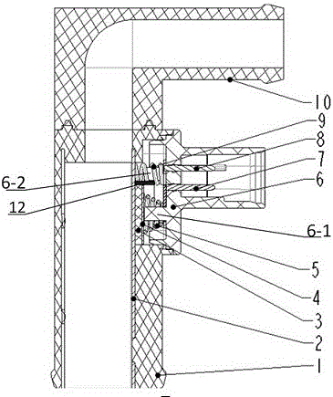
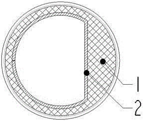
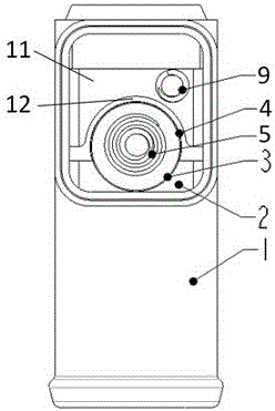
[0027] As attached figure 1 As shown, the crankcase ventilation pipe heating joint of the present invention includes a main casing 1, a secondary casing 10, a thermally conductive copper pipe 2, a plug-in cover 6 and a PTC heating mechanism. The main casing 1 and the secondary casing The inside of 10 forms a pipeline structure, and the connection between the main housing 1 and the secondary housing 10 forms a joint structure. The materials of the main housing 1, the secondary housing 10 and the plug-in cover 6 are all PA66+ GF30 (glass fiber reinforced nylon material) has good injection performance, and the relative angle between the main shell 1 and the secondary shell 10 is adjustable, w...


PUM


Abstract

The invention provides a crankcase ventilation pipeline heating joint. The crankcase ventilation pipeline heating joint comprises shells, a heat conduction metal pipe and a PTC heating mechanism. Joint pipelines are formed in the shells; the heat conduction metal pipe is formed on the inner wall of one of the joint pipelines; the PTC heating mechanism makes contact with the heat conduction metal pipe; and the heat conduction metal pipe is heated at the constant temperature through the PTC heating mechanism. According to the crankcase ventilation pipeline heating joint, by innovatively arranging the heating mechanism at the crankcase ventilation pipeline joint and introducing the PTC heating mechanism, the effect that the crankcase ventilation pipeline joint is prevented from being frozen at the low air temperature is guaranteed, therefore, the problem of engine failure caused by oil seal bulging when the crankcase ventilation pipeline joint is frozen and blocked is effectively prevented, the environment adaptability of an engine is improved, and the service life of the engine is prolonged.

Description

Technical field [0001] The invention relates to a heating joint, in particular to a crankcase ventilation pipe heating joint, and more specifically to a crankcase ventilation pipe heating joint using a PTC heating mechanism, which can effectively prevent the crankcase ventilation pipe joint at lower temperatures The inside is frozen and blocked. Background technique [0002] At present, due to pollutant emission requirements, most engines use closed crankcase ventilation systems, and crankcase exhaust gas can only enter the air intake system through the crankcase ventilation pipe for reburning. In colder areas in winter, when the vehicle is driving, the water vapor contained in the exhaust gas of the flex box is easy to condense into ice in the ventilation pipe joints, and gradually accumulate and block the ventilation pipe joints, resulting in a sharp increase in crankcase pressure and oil seals. Bulge, oil leaks, engine failure. At lower temperatures (below -35°C), optimizing...

Claims


Application Information

Patent Timeline
Patent Type & Authority Applications(China)
IPC IPC(8): F01M13/00F02M31/12
CPCF01M13/00F02M31/12
Inventor 项大伟
Owner CHERY AUTOMOBILE CO LTD
Why Eureka
Try Eureka