Rail pressure regulating valve for common-rail system

A common rail system and regulating valve technology, applied in the field of rail pressure regulating valve, can solve the problems of poor transient response, complex control algorithm, large energy loss, etc. Effect

Inactive Publication Date: 2016-11-16
BEIJING INSTITUTE OF TECHNOLOGYGY
View PDF10 Cites 4 Cited by
  • Summary
  • Abstract
  • Description
  • Claims
  • Application Information

AI Technical Summary

Problems solved by technology

[0007] The purpose of the present invention is to solve the problems of poor transient response, large energy loss and complicated control algorithm in the prior art, and provide a rail pressure re

Method used


Image

  • Rail pressure regulating valve for common-rail system

Examples


Example Embodiment

[0023] In order to better illustrate the purpose and advantages of the present invention, the content of the present invention will be further described below with reference to the drawings and examples.

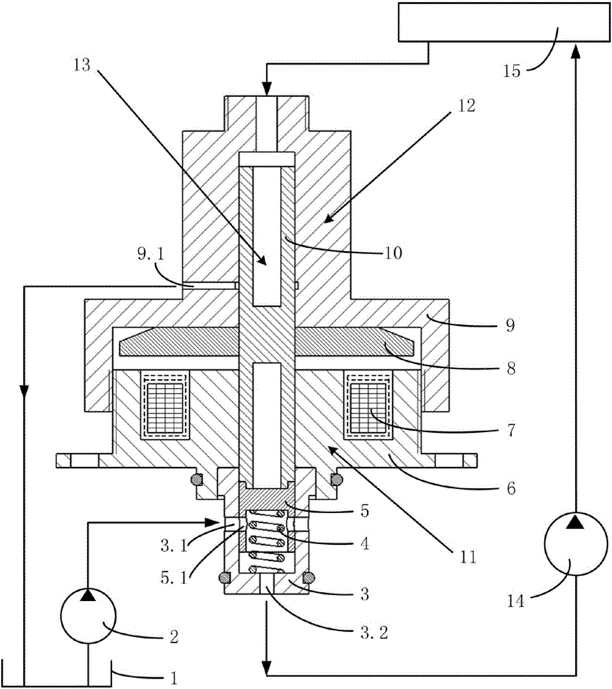
[0024] A rail pressure regulating valve 13 used in a common rail system includes a metering valve 11 and a feedback valve 12.

[0025] The metering valve 11 is composed of a valve body 3, a spring 4, a valve core 5, a metering valve housing 6, an excitation coil 7 and a disc armature 8. The valve body 3 is a hollow cylinder with a bottom end sealed, and the center of the bottom end is provided with oil Hole 3.2, an oil inlet 3.1 is provided on the side wall; the spring 4 is placed between the valve body 3 and the valve core 5, and is initially pre-compressed by the valve core 5; the valve core 5 is placed inside the valve body 3 and can be axially The valve core 5 is provided with a throttle hole 5.1. The throttle hole 5.1 matches the oil inlet hole 3.1. The axial movement of the...


PUM


Abstract

The invention relates to a rail pressure regulating valve, in particular to a rail pressure regulating valve for a common-rail system, and belongs to the field of fuel injection systems of internal combustion engines. The rail pressure regulating valve comprises a metering valve and a feedback valve, wherein the metering valve is mounted between the outlet of a low-pressure oil pump and the inlet of a high-pressure oil pump; the feedback valve is connected with a common-rail pipe through a high-pressure oil pipe; the metering valve and the feedback valve are linked through screw threads on a metering valve shell and a feedback valve shell; the upper end of a valve core of the metering valve and the lower end of a valve rod of the feedback valve are rigidly connected together through interference fit; and a disc-type armature of the metering valve and the valve rod of the feedback valve are linked through the screw threads or rigidly connected together through interference fit. The rail pressure regulating valve provided by the invention is served as a feedback rail pressure regulating valve, and has the characteristics that the transient response is quick, the energy loss is low, and the rail pressure control algorithm is greatly simplified.

Description

technical field [0001] The invention relates to a rail pressure regulating valve, in particular to a rail pressure regulating valve used in a common rail system, and belongs to the field of fuel injection systems of internal combustion engines. Background technique [0002] "Energy saving and emission reduction, increasing power density" is the goal that the field of internal combustion engines has been pursuing. The electronically controlled high-pressure common rail fuel injection system (common rail system for short) is the most potential technology in the internal combustion engine industry to achieve this goal. Its biggest feature is that the fuel injection pressure, fuel injection volume, and fuel injection timing can be precisely adjusted and controlled. The essence of the control and adjustment of fuel injection pressure is the control of rail pressure. The rail pressure needs to change according to the operating conditions of the engine, and also needs to be relati...

Claims


Application Information

Patent Timeline
IPC IPC(8): F02M63/00F02M59/34
CPCF02M59/34F02M63/0017F02M63/0049F02M63/0061
Inventor 钱德省廖日东王尚勇向建华
Owner BEIJING INSTITUTE OF TECHNOLOGYGY
Why Eureka
Try Eureka