A force limiting device with damping

A force-limiting and damping technology, applied in springs, shock absorbers, gas shock absorbers, etc., can solve the problems of high sealing performance requirements, difficult promotion and application, and high production costs, and achieve unique functions, promote internal force redistribution, powerful effects

Inactive Publication Date: 2018-06-26
TONGJI UNIV
View PDF6 Cites 0 Cited by
  • Summary
  • Abstract
  • Description
  • Claims
  • Application Information

AI Technical Summary

Problems solved by technology

However, the damping shock absorber needs to use a piston and a damping spring, and the structure is relatively complicated. At the same time, three cavities need to be formed, which requires high sealing performance of the structure. Therefore, the production cost is also high, and it is not easy to popularize and apply.

Method used


Image

  • A force limiting device with damping
  • A force limiting device with damping
  • A force limiting device with damping

Examples


Embodiment 1

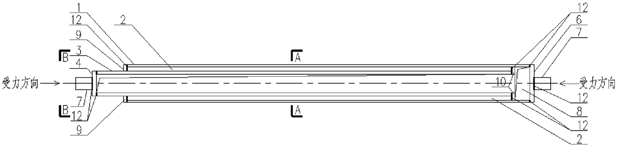
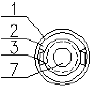
[0058] Such as Figure 1-3 As shown, the limiting force device with damping in this embodiment includes an outer tube 1 and an inner tube 3, the end of the outer tube 1 is connected with a base 6, and a part of the inner tube 3 extends from the head end of the outer tube 1 to the outer tube 1 Inside, the outer end of the inner tube 3 is connected with the upper cover 4, and the base 6 and the upper cover 4 are respectively connected with a connecting piece 7, which is connected to the main structure through the connecting piece 7 during use, and the connecting piece 7 can withstand pressure.

[0059] The limiting force device with damping of this embodiment also includes a metal damping unit 2, the metal damping unit 2 is located between the outer tube 1 and the inner tube 3, and is arranged along the axial direction of the outer tube 1 and the inner tube 3, and one end thereof is connected to the outer tube 3. The tube 1 is fixedly connected, and the other end is fixedly conn...

Embodiment 2

[0068] Such as Figure 4-6 As shown, the force limiting device with damping of this embodiment differs from Embodiment 1 in that:

[0069] In this embodiment, the metal damping unit 2 is four arc-shaped metal slats.

Embodiment 3

[0071] Such as Figure 7-9 As shown, the force limiting device with damping of this embodiment differs from Embodiment 1 in that:

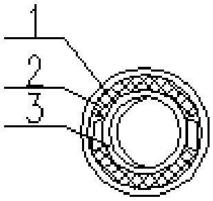
[0072] In this embodiment, the metal damping unit 2 is a circular metal tube.

[0073] Embodiments 1-3 provide that the outer sleeve 1 and the inner tube 3 are circular metal tubes, and the metal damping unit 2 is in the form of arc-shaped metal laths or circular tubes. When in use, the outer sleeve 1 and the inner tube 3 The form is not limited to circular metal tubes, and rectangular metal tubes can also be used, and the metal damping unit 2 can also be in the form of metal laths or rectangular tubes, see embodiments 5-7.


PUM


Abstract

The invention relates to a limiting force device with damping and belongs to a stable control and shock absorption device. The limiting force device comprises an outer casing pipe and an inner pipe. The tail end of the outer casing pipe is connected with a base. One part of the inner pipe stretches into the outer casing pipe from the head end of the outer casing pipe. The outer end of the inner pipe is connected with an upper sealing cover. Each of the base and the upper sealing cover is connected with a connecting piece. During use, the limiting force device is connected to a body structure through the connecting piece, and the connecting piece can bear pressure. The limiting force device further comprises a metal damping unit which is located between the outer casing pipe and the inner pipe and is arranged in the axial direction of the outer casing pipe and the inner pipe. One end of the metal damping unit is fixedly connected with the outer casing pipe, and the other end of the metal damping unit is fixedly connected with the inner pipe. A certain movement distance is reserved between the inner end of the inner pipe and the base, so that a movement cavity is formed among the side wall of the outer casing pipe, the inner end of the inner pipe and the base. Compared with the prior art, the limiting force device integrates a limiting force function and a damping function, serves as a structure energy dissipation, shock absorbing and stable control element and has the beneficial effects of being powerful in function, long in service life, safe, reliable and the like.

Description

technical field [0001] The invention relates to an energy dissipation and shock absorbing device, in particular to a force limiting device with damping. Background technique [0002] At present, many dampers only have a damping effect, and the limiting force device only has the function of bearing a fixed pressure load, which has a single function and limits the scope of use. [0003] Chinese patent CN105041957A discloses a spring air pressure damping shock absorber, which belongs to the field of shock absorbers. The invention includes an outer tube, an inner tube and a piston rod. The inner tube is arranged inside the outer tube, and an inner tube piston is arranged on one end of the inner tube inside the outer tube, and the inner tube piston cooperates with the inner wall of the outer tube to form a sealed cavity A. ; One end of the piston rod is fixed on the end of the outer tube, the other end passes through the inner tube piston and extends into the sealed inner tube, ...

Claims


Application Information

Patent Timeline
Patent Type & Authority Patents(China)
IPC IPC(8): F16F9/02F16F9/32
CPCF16F9/0209F16F9/3207
Inventor 胡振青邓长根
Owner TONGJI UNIV
Why Eureka
Try Eureka