Al technical title is built by PatSnap Al team. It summarizes the technical point description of the patent document.
A technology for drying equipment and sugar cubes, applied in the field of brown sugar cube drying equipment, can solve the problems of small size of drying equipment, inability to cover the drying box, poor water evaporation effect, etc. The mold is labor-saving and fast, and the dehumidification effect is good.
Inactive Publication Date: 2016-11-16
昆明逵昌生物科技有限公司
View PDF4 Cites 4 Cited by
Summary
Abstract
Description
Claims
Application Information
AI Technical Summary
This helps you quickly interpret patents by identifying the three key elements:
Problems solved by technology
Method used
Benefits of technology
Problems solved by technology
At present, the brown sugar block drying equipment has the following disadvantages: First, in order to ensure that the brown sugar block is heated evenly to the greatest extent, the drying equipment is small in size and low in drying efficiency. Mass production requires many sets of equipment to work at the same time and occupies a large area; Most of the drying equipment is hot air drying. In order to take away the evaporated water, the hot air needs to be continuously discharged while entering the hot air. However, the hot air inlet and outlet of the drying equipment are fixed, and the air flow direction is fixed, so it cannot spread throughout the entire drying box. It is impossible to realize the internal circulation of hot air in the box, resulting in insufficient heating uniformity and poor water evaporation effect; third, the mold support frame of the drying equipment is fixed, and can only clamp a molding mold of one specification, with a single structure and brown sugar The quality of the forming mold is relatively large, and it is inconvenient for the staff to put the mold into or take out the drying box
Method used
Image
Click on the blue label to locate the original text in one second.
Reading with bidirectional positioning of images and text.
Examples
Embodiment Construction
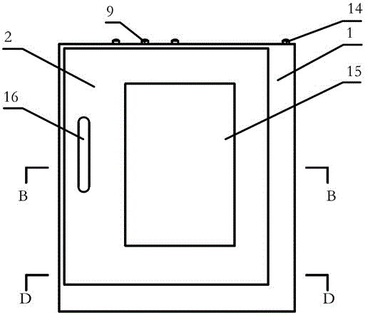
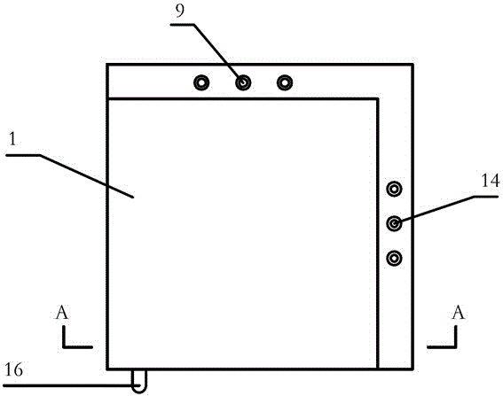
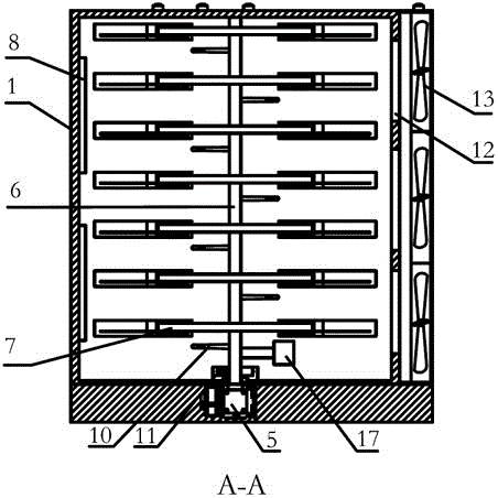
[0031] Such as Figure 1-Figure 9 As shown, a brown sugar block drying equipment includes a box body 1, a box door 2, an induced draft fan 3, a heating rod 4, a gas booster 5, a tracheal shaft 6, a mold carrier 7, a heater 8, and a control switch 9. , Air intake reverse tube 10, stall positioner 11, air outlet 12, air outlet fan 13, and fan switch 14, the side of the box body 1 is provided with a box door 2, and the upper end of the box body 1 is provided with a control switch 9 and a fan switch 14. The control switch 9 includes a fan switch, a heating rod switch, and a heater switch. The lower end of the box body 1 opposite to the box door 2 is provided with an air inlet bin, and an induced draft fan is sequentially arranged in the air inlet bin 3 and heating rod 4, the induced draft fan 3 is controlled by the fan switch, the heating rod 4 is controlled by the heating rod switch, the air inlet bin is connected to the gas booster 5, and the gas booster 5 is connected to the tra...
PUM
Abstract
The invention particularly relates to brown sugar drying equipment. The brown sugar drying equipment comprises a box body, a box door, an induced draft fan, heating rods, a gas booster, an air tube shaft, die holder frames, a heater, control switches, an air intake reverse thrust tube, a rotation stop locator, air outlets, air outlet fans and fan switches. The brown sugar drying equipment is large in size, makes the best of space resources to convert into production efficiency, and is suitable for batch production of brown sugar; internal circulation of air in the box body is promoted, temperature in the box body is quickly unified, the brown sugar moisture evaporation effect is good, the included angle directions of the air outlets are opposite to the internal circulation direction of hot air in the box body, and hot air cannot be discharged from the air outlets at the first time, so that heat energy can be utilized to the utmost degree, and the dehumidification effect is good; dies of different specifications can be fixed firmly and securely, the operation is convenient, and the dies can be quickly taken out with less effort; and before and after drying operation, when the dies are placed on or taken away from the die holder frames, the die holder frame on the circumference of each layer right faces the box door, so that convenience is brought for workers to place or take out the dies.
Description
Technical field [0001] The invention belongs to the field of brown sugar processing equipment, and specifically relates to a brown sugar block drying equipment. Background technique [0002] In brown sugar block processing, brown sugar block drying is the process of dehydrating and drying the brown sugar block formed in the brown sugar block forming mold. At present, brown sugar block drying equipment has the following shortcomings: First, in order to ensure that the brown sugar block is heated uniformly to the greatest extent, the drying equipment is small in size and low in drying efficiency. Mass production requires many equipment to work at the same time, and it covers a large area; The drying equipment is mostly hot air drying. In order to take away the evaporated water, the hot air needs to be continuously discharged while the hot air is in. However, the hot air inlet and outlet of the drying equipment are fixed, and the air flow direction is fixed, so it cannot cover the e...
Claims
Application Information
Patent Timeline
Application Date:The date an application was filed.
Publication Date:The date a patent or application was officially published.
First Publication Date:The earliest publication date of a patent with the same application number.
Issue Date:Publication date of the patent grant document.
PCT Entry Date:The Entry date of PCT National Phase.
Estimated Expiry Date:The statutory expiry date of a patent right according to the Patent Law, and it is the longest term of protection that the patent right can achieve without the termination of the patent right due to other reasons(Term extension factor has been taken into account ).
Invalid Date:Actual expiry date is based on effective date or publication date of legal transaction data of invalid patent.