Non-coupling pre-splitting explosive charging device and using method
A technology of charging and pre-splitting, applied in blasting and other directions, can solve the problems of labor consumption, time-consuming, complicated charging process, etc., and achieve the effects of reducing dust volume, being convenient to carry, and having a wide range of sources.
- Summary
- Abstract
- Description
- Claims
- Application Information
AI Technical Summary
Problems solved by technology
Method used
Image

Examples
Embodiment 1
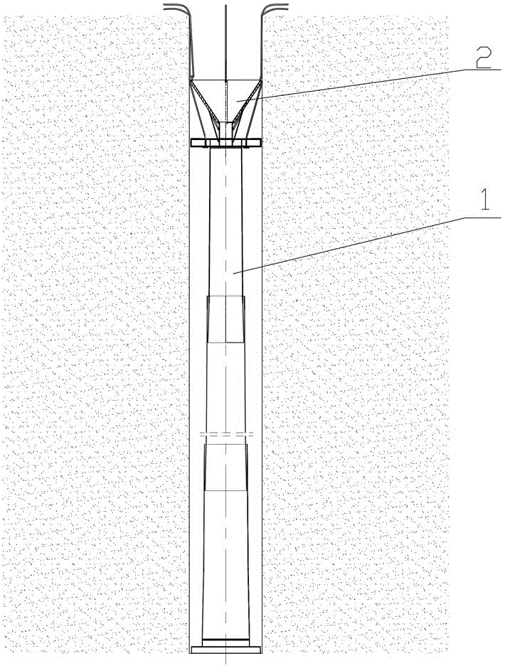
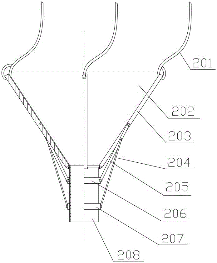
[0030] like figure 1 , 2 , 3, an uncoupled pre-split charging device is composed of a variable-diameter uncoupled pre-split charging cartridge 1 and an umbrella-shaped charging device 2 .
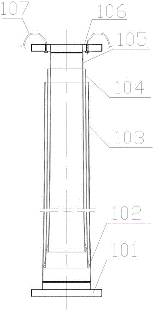
[0031] The variable-diameter uncoupled pre-split cartridge 1 consists of a bottom cover 101, a bottom barrel 103 threadedly connected with the bottom cover 101, and a group of intermediate barrels 104 in the bottom barrel 103, which are inserted in this group in turn. The top cylinder 105 in the intermediate cylinder 104 is composed of a central positioning ring 106 threadedly connected to the top cylinder 105 and a manual pull rope 107 provided on the central positioning ring 106. The bottom outer surface of the intermediate cylinder 104 and the top cylinder 105 All have rubber anti-slip sleeves 102, and the diameter of the cylinders of the group of intermediate cylinders 104 decreases sequentially from bottom to top;
[0032] The centering ring 106 should be a set of spare parts with di...
Embodiment 2
[0042] The test pre-split hole depth is 15 m, the pre-split hole diameter is 250 mm, and the blasting hole filling length is 4.5 m. In the device of implementation 1, the cone angle of the truncated conical tube with variable diameter not coupled to the pre-split cartridge is 0.4°, the diameter of the upper end of the top tube is 93 mm, and the diameter of the lower end of the bottom tube is 240 mm, including each tube in the middle tube. The length is 1.64 m, and there are 7 cylinders in total; the diameter of the cylinder of the umbrella-shaped chargeer used is 50 mm.
[0043] The steps of the specific use method of the uncoupled pre-split charging device are as follows:
[0044] (1) Assemble a top cylinder, a bottom cylinder and 5 intermediate cylinders into a variable-diameter uncoupled pre-split cartridge, install the bottom cover on the lower end of the bottom cylinder and screw it tightly;
[0045] (2) Put the combined cartridges into the orifice of the gun hole, pull ...
Embodiment 3
[0051] The test pre-split hole depth is 12 m, the pre-split hole diameter is 220 mm, and the blast hole filling length is 3.6 m. In the device of implementation 1, the cone angle of the conical tube with variable diameter not coupled with the pre-split cartridge is 0.4°, the diameter of the upper end of the top tube is 108 mm, and the diameter of the lower end of the bottom tube is 210 mm, including the diameter of each tube of the middle tube. The length is 1.34 m, and there are 7 cylinders in total; the diameter of the cylinder with the umbrella-shaped charge in the hole is 60 mm.
[0052] The steps of the specific use method of the uncoupled pre-split charging device are as follows:
[0053] (1) Select one top cylinder, one bottom cylinder and 5 intermediate cylinders, assemble them into variable diameter uncoupled pre-split cartridges, install the bottom cover at the lower end of the bottom cylinder and screw it tightly;
[0054] (2) Put the combined cartridges into the o...
PUM
 Abstract
Description
Claims
Application Information
 - R&D
- Intellectual Property
- Life Sciences
- Materials
- Tech Scout
- Unparalleled Data Quality
- Higher Quality Content
- 60% Fewer Hallucinations
Browse by: Latest US Patents, China's latest patents, Technical Efficacy Thesaurus, Application Domain, Technology Topic, Popular Technical Reports.
© 2025 PatSnap. All rights reserved.Legal|Privacy policy|Modern Slavery Act Transparency Statement|Sitemap|About US| Contact US: help@patsnap.com