Device and method for measuring concentricity of coupling between turbine and electric generator of turbine set

A technology for a steam turbine unit and a measuring device, which is applied to mechanical measuring devices, measuring devices, and mechanical devices, etc., can solve the problems of inaccurate measurement results, inability to measure concentricity, screw slippage, etc. Easy to operate effect

Active Publication Date: 2016-11-16
MCC5 GROUP CORP SHANGHAI
View PDF5 Cites 5 Cited by
  • Summary
  • Abstract
  • Description
  • Claims
  • Application Information

AI Technical Summary

Problems solved by technology

The disadvantage of this device is that the screw needs to be stuck in the gear groove. Since the height of the gear groove is not large, the screw is easy to slip out of the groove when turning, so that the concentricity cannot be measured; The 12mm screw is small and easily deformed, resulting in inaccurate measurement results
[0003] Therefore, there are above-mentioned inconveniences and problems in the known concentricity measuring device and method of steam turbine and generator coupling of steam turbine unit

Method used


Image

  • Device and method for measuring concentricity of coupling between turbine and electric generator of turbine set
  • Device and method for measuring concentricity of coupling between turbine and electric generator of turbine set
  • Device and method for measuring concentricity of coupling between turbine and electric generator of turbine set

Examples


Embodiment 1

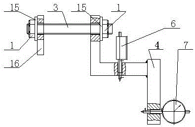
[0032] The device for measuring the concentricity of the shaft coupling between the steam turbine and the generator of the steam turbine unit of the present invention includes two horizontal bars and two vertical bars.

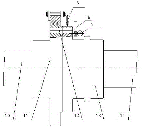
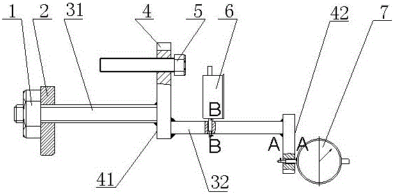
[0033] see now Figure 3-Figure 5 , image 3 It is a schematic structural diagram of a concentricity detection device according to an embodiment of the present invention, Figure 4 for image 3 A-A sectional view in, Figure 5 for image 3 B-B sectional view in . As shown in the figure, one end of the first horizontal bar 31 in the two horizontal bars is provided with a thread, and the thread is equipped with a nut 1, and the other end is solidly welded to the lower part of the first vertical bar 41 in the two vertical bars, and is connected to the first vertical bar 41. The rod is vertical, the first vertical rod is a dial indicator support 4, the top of the first vertical rod is horizontally provided with a threaded hole, and the first jacking screw 5 i...

Embodiment 2

[0037] The method for measuring the concentricity of the steam turbine and the generator coupling of the steam turbine unit of the present invention comprises the following steps:

[0038] a. Clamp the first crossbar 31 with a diameter of 24mm in the groove of the gear of the coupling, and tighten the nut 1 at the threaded end to fasten the backing plate 2;

[0039] b. Tighten the first jacking screw 5 so that the bracket 4 of the dial gauge is tight against the turning gear 12;

[0040] c. Install the first percentile gauge 6 and the second percentile gauge 7;

[0041] d. Rotate the coupling between the steam turbine and the generator to make the coupling rotate, and read the readings of the first and second dial gauges by conventional methods, so that the first dial gauge 6 and the second dial gauge The measuring heads in Subtable 7 respectively measure the shape and position error of the side and end face of the half-coupling on the generator side, that is, the concentrici...


PUM


Abstract

The invention relates to a device and a method for measuring the concentricity of a coupling between a turbine and an electric generator of a turbine set. The device comprises two transverse rods and two vertical rods. The device is characterized in that one end of a first transverse rod (31) of the two transverse rods is provided with threads, the other end of the first transverse rod (31) is fixedly welded to the lower part of a first vertical rod (41) of the two vertical rods, the first vertical rod is a dial indicator bracket (4), a threaded hole is horizontally formed in the top end of the first vertical rod, a first puller bolt (5) is arranged in the threaded hole, the bottom end of the first vertical rod is fixedly welded to one end of a second transverse rod (32) of the two transverse rods, a through hole is vertically formed in the middle of the second transverse rod, a first dial indicator (6) is arranged in the through hole, the other end of the second transverse rod is fixedly welded to the upper end of a second vertical rod (42), a through hole is horizontally formed in the lower end of the second vertical rod, and a second dial indicator (7) is arranged in the horizontal through hole. The device has the advantages that the structure is simple, the production is convenient, and the concentricity is accurately measured. The device is applicable to the adjustment of concentricity of couplings between all turbines and electric generators.

Description

technical field [0001] The invention relates to a device for measuring the concentricity of a coupling, in particular to a device and method for measuring the concentricity of a coupling between a steam turbine and a generator of a steam turbine unit. Background technique [0002] Turbogenerators are widely assembled and must be overhauled after working for a period of time. During the overhaul, it is necessary to re-measure and adjust the concentricity of the coupling between the turbine rotor and the generator rotor. To measure the concentricity, the dial indicator method is generally used. figure 1 It is a structural schematic diagram of a known concentricity detection device shipped with a steam turbine, figure 2 for figure 1 A-A sectional view in, image 3 for figure 1 B-B sectional view in . When the concentricity detection device is used, the screw rod is firstly clamped in the groove of the turning gear of the shaft coupling. Then install the bracket and steel...

Claims


Application Information

Patent Timeline
Patent Type & Authority Applications(China)
IPC IPC(8): G01B5/252
CPCG01B5/252
Inventor 童成明
Owner MCC5 GROUP CORP SHANGHAI
Why Eureka
Try Eureka