Nuclear rod pose automatic identification device and method

A nuclear fuel rod and automatic identification technology, which is applied to measurement devices, optical devices, instruments, etc., can solve the problems of not referring to the technology directly related to the automatic assembly of nuclear fuel rod bundles, so as to omit the three-dimensional object reconstruction link, which is not easy. Image occlusion, the effect of improving image processing speed

Active Publication Date: 2016-11-16
HARBIN INST OF TECH
View PDF4 Cites 12 Cited by
  • Summary
  • Abstract
  • Description
  • Claims
  • Application Information

AI Technical Summary

Problems solved by technology

However, no technology directly related to the automated assembly of nuclear fuel bundles has been found

Method used


Image

  • Nuclear rod pose automatic identification device and method
  • Nuclear rod pose automatic identification device and method
  • Nuclear rod pose automatic identification device and method

Examples


specific Embodiment 1

[0065] This embodiment is an embodiment of a device for automatically identifying the position and orientation of nuclear fuel rods.

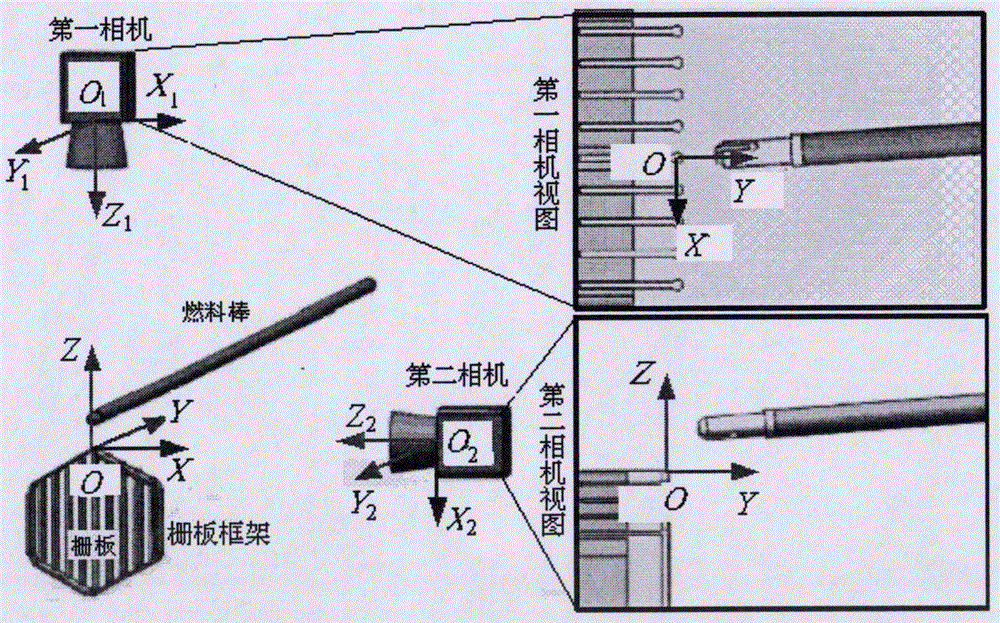
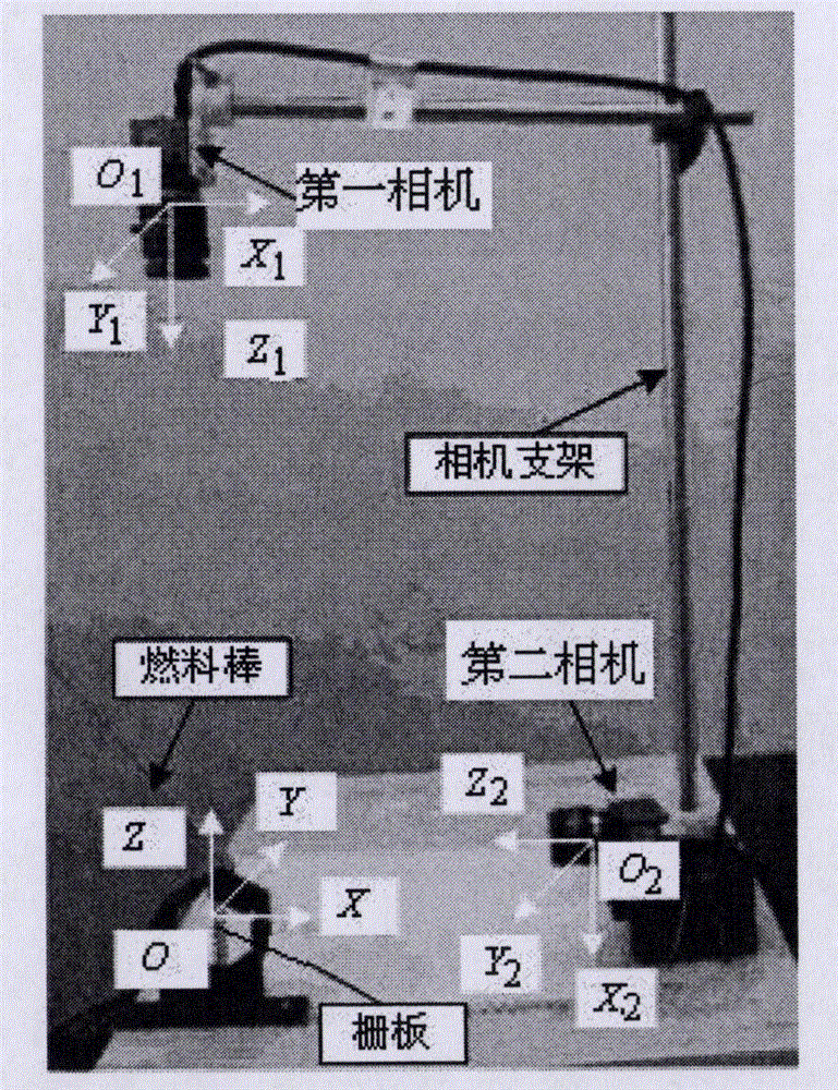
[0066] The nuclear fuel rod position and posture automatic recognition device of this embodiment, the schematic diagram and the physical diagram are respectively as follows figure 2 and image 3 shown. The nuclear fuel rod pose automatic identification device includes a first camera and a second camera arranged orthogonally,

[0067] The direction of the optical axis of the first camera is parallel to the Z axis, and the abscissa and ordinate of the image are respectively parallel to the X axis and the Y axis, which are used to detect the displacement information of the nuclear fuel rod lower end plug relative to the grid plate in the X axis direction and the Y axis direction , and the deflection angle α of the lower end plug opening slot rotating around the Y axis and the direction angle θ of the lower end plug axis in the XOY plane;

[00...

specific Embodiment 2

[0072] This embodiment is an embodiment of a device for automatically identifying the position and orientation of nuclear fuel rods.

[0073] The device for automatically recognizing the pose and posture of nuclear fuel rods in this embodiment, on the basis of the first embodiment, limits the minimum resolutions of the first camera and the second camera.

[0074] Define the diameter of the lower end plug of the nuclear fuel rod as D, the length of the opening slot as L, and the width of the opening slot as W 1 , the width of the grid frame is W, the height is H, the thickness of the grid is T, and the safety distance between the initial position of the lower end plug and the grid frame is D S , the minimum difference between the thickness of the grid plate and the width of the opening slot is Δ, that is, W 1 -T≥Δ, the image recognition accuracy is δ, take δ=Δ / 4;

[0075] The minimum resolution of the first camera is R A1 × R A2 , where R A1 ≥W / δ,R A2 ≥(2L+D S ) / δ;

[0...

specific Embodiment 3

[0086] This embodiment is an embodiment of a device for automatically identifying the position and orientation of nuclear fuel rods.

[0087] The nuclear fuel rod pose automatic recognition device of this embodiment, on the basis of specific embodiments 1 and 2, calibrates the internal and external parameters of the first camera and the second camera, including the following steps:

[0088] Step a, use the Zhang Zhengyou calibration method to calibrate the internal parameter f of the first camera x1 , f y1 , u 01 and v 01 ;

[0089] Step b. Use the Zhang Zhengyou calibration method to calibrate the internal parameter f of the second camera x2 , f y2 , u 02 and v 02 ;

[0090] The order of step a and step b can be replaced or carried out simultaneously;

[0091] Step c, photographing the same calibration board with the first camera and the second camera, respectively obtaining the first image of the calibration board and the second image of the calibration board;

[0...


PUM


Abstract

The invention provides a nuclear rod pose automatic identification device and method and belongs to the technical field of machine vision and nuclear power equipment manufacturing automation. The device comprises a first camera and a second camera which are orthogonally arranged. The optical axis of the first camera is parallel to a Z axis, and horizontal and vertical coordinates of an image are parallel to an X axis and a Y axis respectively. The optical axis of the second camera is parallel to the X axis, and horizontal and vertical coordinates of an image are parallel to the Y axis and the Z axis respectively. The method comprises steps that firstly, image features of a lower plug of a nuclear rod are extracted, then space pose information of the lower plug of the nuclear rod is calculated, and finally the nuclear rod is assembled according to the space pose information. The automatic identification device and method can monitor shape change and pose change of the nuclear rod, provide a device basis and a theoretical basis for automatic assembly of the nuclear rod and a grid plate, and is beneficial for achieving automatic assembly of nuclear rod clusters. The safety of nuclear power equipment manufacturing is improved, and the intelligent level of nuclear power equipment manufacturing is greatly improved.

Description

technical field [0001] The invention relates to a device and method for automatically identifying the position and posture of nuclear fuel rods, which belong to the technical field of machine vision and nuclear power equipment manufacturing automation. Background technique [0002] With the continuous expansion of the demand for clean energy around the world, the nuclear power industry is also developing rapidly. The nuclear fuel rod bundle is the core component of the nuclear power equipment, which is assembled from the nuclear fuel rods and the grid frame (by plugging the lower end plugs of the nuclear fuel rods and the grid plate on the grid frame), such as figure 1 shown. Because nuclear fuel rods will produce nuclear radiation, and nuclear radiation will not only cause serious pollution to the environment, but also cause great harm to the health of practitioners, therefore, it is necessary to automatically assemble nuclear fuel rods and grids to ensure the safety of nu...

Claims


Application Information

Patent Timeline
Patent Type & Authority Applications(China)
IPC IPC(8): G01B11/00
CPCG01B11/002G01B11/24
Inventor 任秉银柴立仁魏坤
Owner HARBIN INST OF TECH
Why Eureka
Try Eureka